Unbacked fabric transport and condition system

a technology of transport and condition system and unbacked fabric, which is applied in the direction of transportation and packaging, textile treatment carrier, dyeing process, etc., can solve the problems of significant environmental unfriendly waste stream, time-consuming and environmental protection, and industrial fabric printing process prohibitive for small-scale users to use, so as to avoid damage to the print head

Inactive Publication Date: 2010-05-04
HEWLETT PACKARD DEV CO LP
View PDF24 Cites 35 Cited by
  • Summary
  • Abstract
  • Description
  • Claims
  • Application Information

AI Technical Summary

Problems solved by technology

This cleanup process is time intensive and environmentally unfriendly because it produces a large amount of effluent stream during the cleanup process.
However, gluing the fabric to the belt is an extremely dirty process that creates a significant environmentally unfriendly waste stream resulting from the gluing process and the subsequent washing and stripping processes.
These inherent problems make industrial fabric printing processes prohibitive for use by smaller-scale users in the short run or sample printing situations.
Furthermore the need for short and sample quantity runs generally exists in an office or a store setting, which generally is not designed to handle, treat and dispose of industrial waste streams.
However, the use of off-line paper backings may be costly, time consuming, and may limit the range of fabrics that may be fed through the ink-jet printer.
Furthermore, the fabric may be damaged when the fabric is removed from the paper backing.
The fundamental nature of woven fabrics makes feeding the unbacked fabric and printing a pattern on the unbacked fabric more complex than traditional ink-jet printing on paper.
These factors prohibit the unbacked fabrics from moving accurately and uniformly through the printing processes using standard media-moving machines used in the traditional ink-jet printers.

Method used


Image

  • Unbacked fabric transport and condition system
  • Unbacked fabric transport and condition system
  • Unbacked fabric transport and condition system

Examples


first embodiment

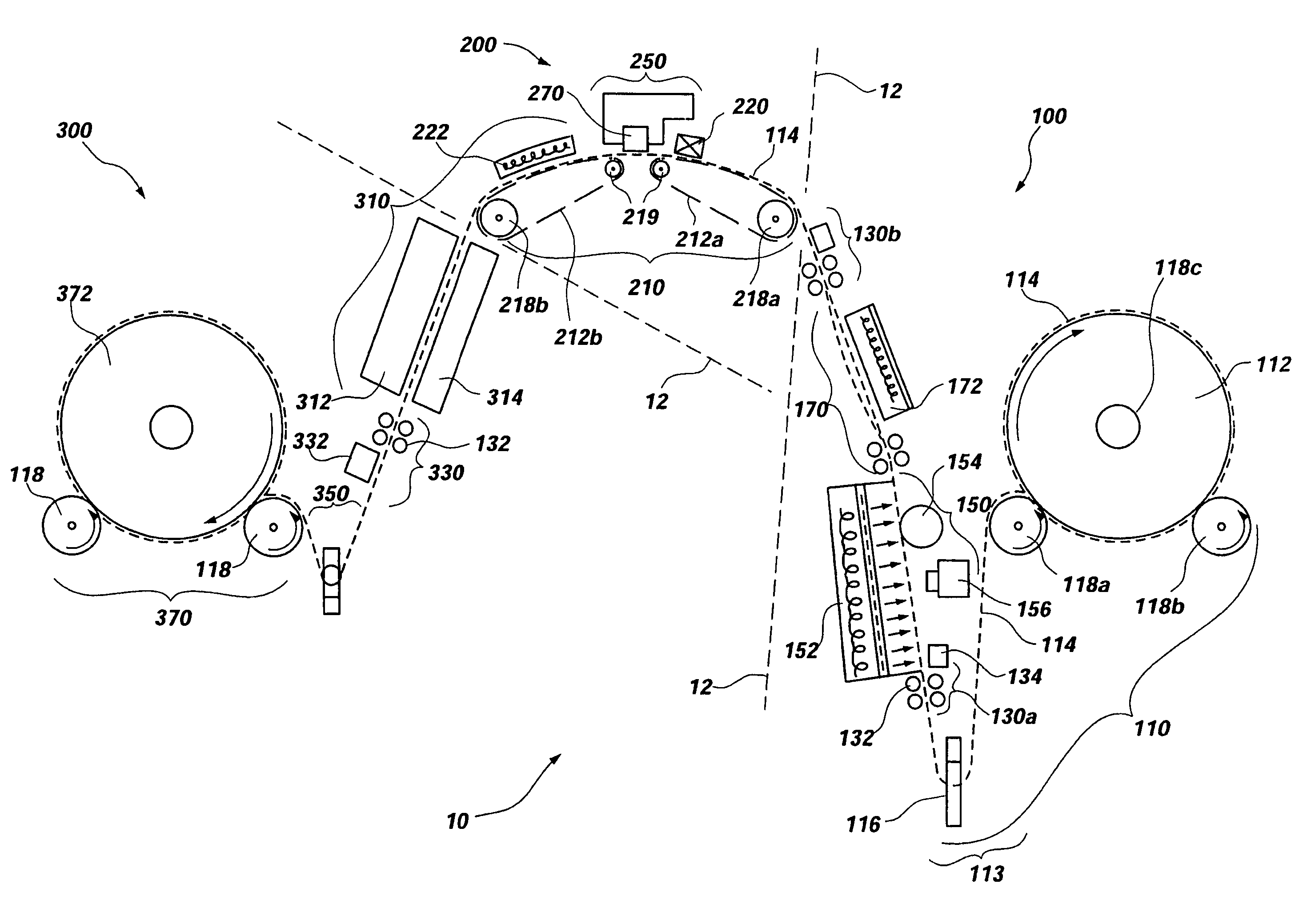
[0059]Referring now to FIG. 5, there is shown an expanded perspective view of the fabric characterization and tension control subsystem 130 located just ahead of components used in the irregularity detection and removal subsystem 150. As illustrated, the irregularity detection and removal system 150 includes a steam table 152 and an ironing roller 154. Once the fabric 114 is characterized by the fabric characterization and tension control subsystem 130, the fabric 114 is moved in a direction illustrated by arrow 14. The fabric 114 crosses the steam table 152 and is ironed with the ironing roller 154 to remove wrinkles and creases. It will be apparent that steam tables 152 and ironing rollers 154 are well known in the art. Accordingly, any steam table 152 and ironing roller 154 that performs functions the same as, or equivalent to, the steam table 152 and ironing roller 154 described herein are meant to be encompassed by the present invention.

second embodiment

[0060]Referring to FIG. 6, there is shown an expanded perspective view of the fabric characterization and tension control subsystem 130 in relation to the irregularity detection and crease removal subsystem 150. As illustrated, the fabric characterization and tension control subsystem 130 includes skewed rollers 132 and drive motors 136 to drive the skewed rollers 132. Also included are a bowed roller 138 and a bowed roller drive motor 139. The bowed roller 138 is used to remove soft creases and provide a light cross-web tension to the fabric 114. Once the soft creases are removed, the fabric 114 may be stretched in multiple directions by the skewed rollers 132 and bowed roller 138 before the fabric 114 is transported to the steam table 152.

[0061]Additionally, the skewed rollers 132 may provide web guidance of the fabric 114 when used in conjunction with the CCD array 134, as illustrated in FIG. 5. It will be appreciated that depending on the type of fabric 114 in the UFTCS 10, the ...


PUM


Abstract

An unbacked transport and conditioning printing system for printing a pattern on a fabric is disclosed. The system includes a fabric characterization and tension control subsystem for gathering information on variations in the fabric and an irregularity detection subsystem for detecting irregularities in the fabric, as well as, crease detection and removal. The fabric passes through a fabric drying and conditioning subsystem for characterization of the fabric. The system also includes a fabric control subsystem for advancing the fabric through a print zone, where a pattern is printed on an unbacked fabric. The fabric is transported through a drying and post-processing subsystem and a closed-loop color control subsystem.

Description

[0001]This is a division of application Ser. No. 10 / 388,060, filed Mar. 12, 2003 now U.S. Pat. No. 6,988,797.FIELD OF THE INVENTION[0002]The present invention generally relates to textile printing systems.BACKGROUND OF THE INVENTION[0003]In the fabric printing industry, fabrics are typically colored with coloring agents, such as dyes or pigments, using a screen printing technology. Most large-scale fabric printing operations employ rotary screen printing technologies that utilize patterns incorporated into fine metal screens that are shaped into cylindrical forms. The coloring agents, are often in a fluid paste form, are pumped through dedicated tubing into the interior of fine cylindrical metal screens and are subsequently transferred to the fabric through the patterned pathways in the fine metal screens by a squeegee that presses the paste through the screens and onto the fabric. After each screen print run, with each color way (i.e., a color variant of the same pattern that uses ...

Claims


Application Information

Patent Timeline
Patent Type & Authority Patents(United States)
IPC IPC(8): B41J15/04B41J2/01B41J3/407B41J11/00B41J11/42B41J15/16B65H26/02D06B23/04D06P5/20D06P5/30D06P7/00
CPCB41J3/4078B41J11/0005B41J11/002D06P5/30B41J15/04B41J15/16B41J11/007B41J11/0022B41J2203/011
Inventor SAMII, MOHAMMAD MVAN VEEN, MARK A.SCHMIDT, JACK H
Owner HEWLETT PACKARD DEV CO LP
Why Eureka
Try Eureka