Controlled force impacting device

a technology of impacting device and controlled force, which is applied in the field of impacting device, can solve the problems of unfavorable use of excessive force by surgeons or assistants, affecting the safety of patients, and general brittleness of ceramic components, etc., and achieves the effect of reducing the tendency to use excessive force and being relatively simple and inexpensiv

Active Publication Date: 2010-05-04
DEPUY PROD INC
View PDF21 Cites 37 Cited by
  • Summary
  • Abstract
  • Description
  • Claims
  • Application Information

AI Technical Summary

Benefits of technology

[0020]The above embodiments may be used to ensure that sufficient force has been applied to lock a Morse taper arrangement. As such, the above embodiments provide the advantage of reducing the tendency to use undesired excessive force. Moreover, the above embodiments may be implemented relatively simply and inexpensively. The controlled force impact tool and method may further be used for other surgical purposes in which impact force is advantageously limited, such as for assembling components that employ non-Morse taper connecting features.

Problems solved by technology

Often, in order to be sure that the Morse taper had locked, the surgeon or assistant would use excessive force.
The use of excessive force is undesirable because of the potential for damage to the bone tissue or the implant device.
While providing many benefits over replacement components made from, for example, cobalt chrome, the ceramic components are generally more brittle.
Accordingly, even surgeons adept at forming Morse taper locks using materials such as cobalt chrome may use excessive force when attempting to form a Morse taper lock with a ceramic replacement part.

Method used


Image

  • Controlled force impacting device
  • Controlled force impacting device
  • Controlled force impacting device

Examples


Embodiment Construction

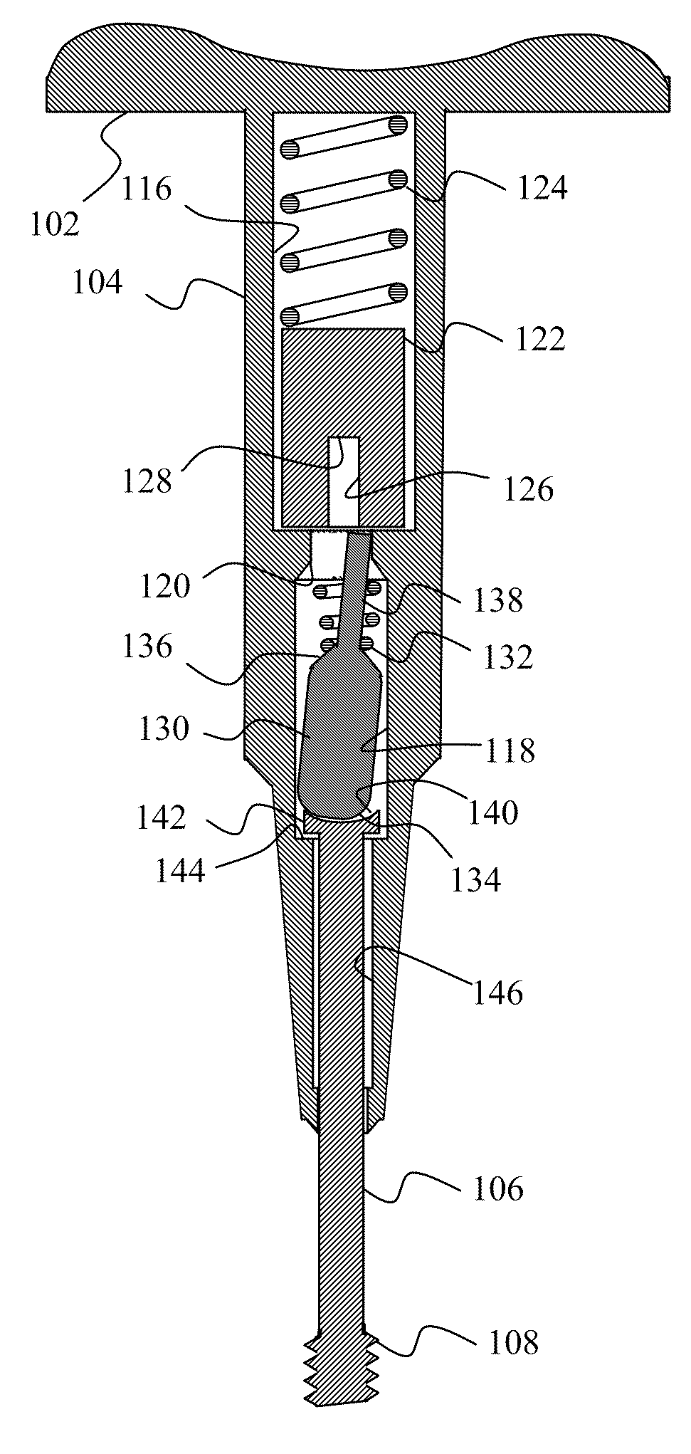
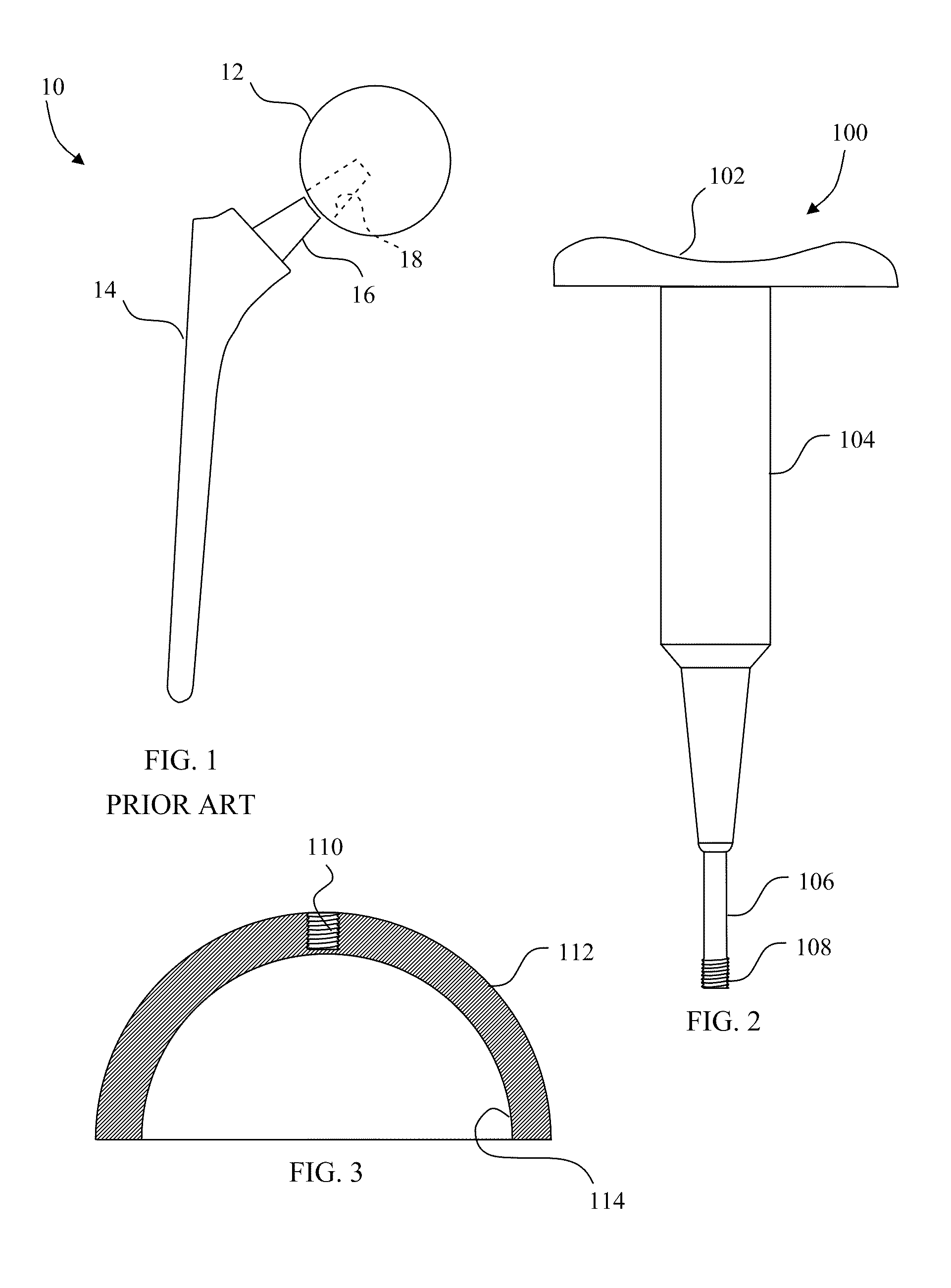
[0039]FIG. 2 shows a controlled force impacting tool 100 according to the invention having a contoured handle 102 and a housing 104 extending therefrom. An impacting rod 106 extends forwardly of the housing 104. The impacting rod 106 includes a threaded distal end 108 that engages a threaded portion 110 of an appropriate impacting tip 112 as shown in FIG. 3. The impacting tip 112 includes a curvilinear internal cavity 114 conformed to mate with a replacement component such as the femoral head 12. In accordance with the present invention, a plurality of impacting tips may be provided, such as in a kit. Each of the plurality of impacting tips may be configured to mate respectively with one of a plurality of replacement components of different types and of different sizes.

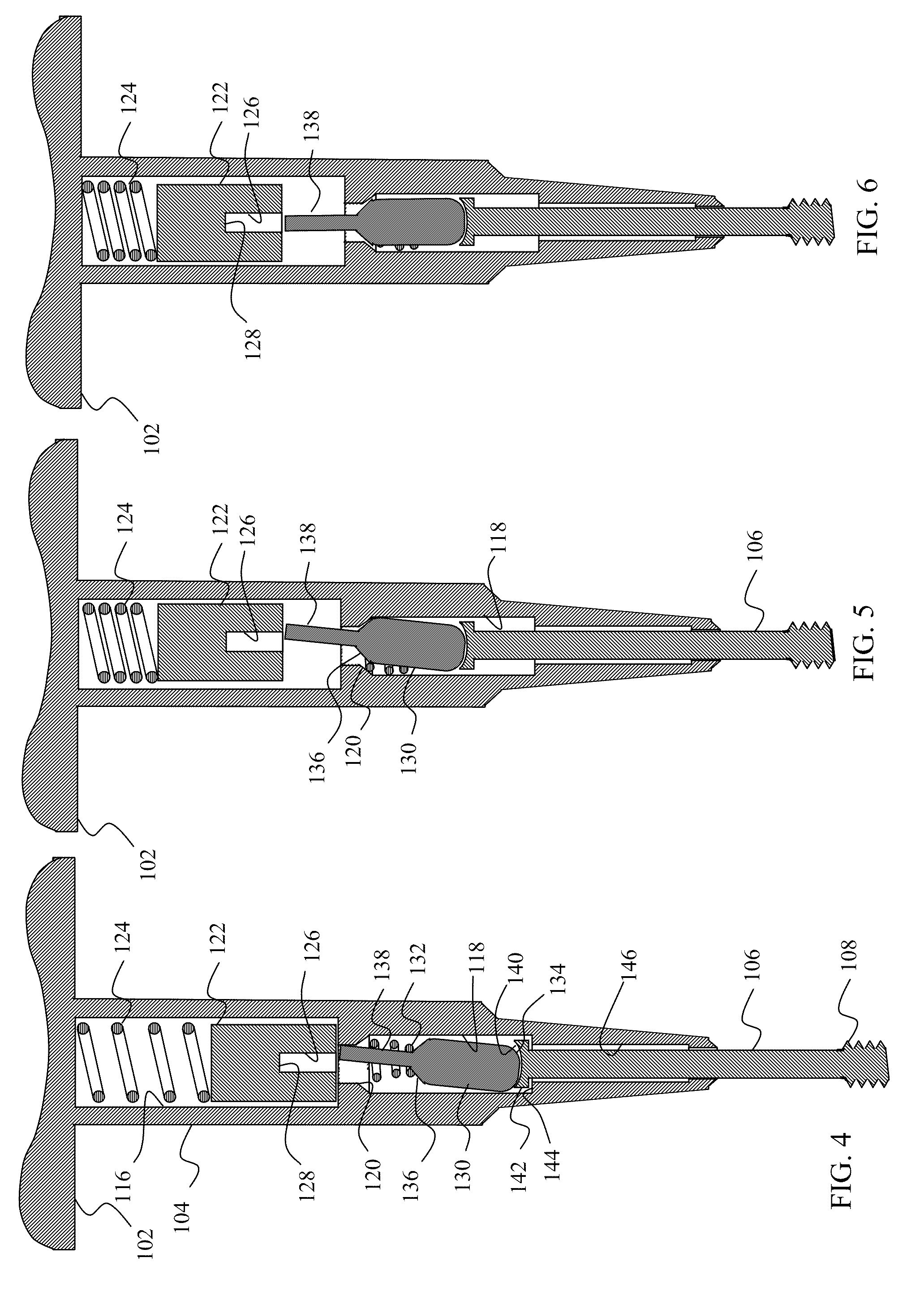
[0040]The internal components of the impacting tool 100 are best seen in FIGS. 4-6. The housing 104 is hollow. An impacting spring compartment 116 is separated from a push rod compartment 118 by a centering hole 120. ...


PUM


Abstract

An impacting tool includes a trigger mechanism that is activated when a predetermined amount of energy is stored in the impacting tool. When the impacting tool is activated, the stored energy is precipitously discharged through an impact rod which is configured to transfer a controlled force to an orthopaedic component.

Description

FIELD OF THE INVENTION[0001]The present invention relates to impacting devices, such as those used to provide impact force to a prosthetic component in order to secure the prosthetic component to another device or to tissue.BACKGROUND OF THE INVENTION[0002]Many orthopaedic procedures involve the implantation of prosthetic devices to replace badly damaged or diseased bone tissue. Common orthopaedic procedures that involve prosthetic devices include total or partial hip, knee and shoulder replacement. For example, a hip replacement often involves a prosthetic femoral implant. The femoral implant usually includes a rigid stem that is secured within the natural femur bone tissue. The femoral implant further includes a rounded head that is received by, and may pivot within, a natural or artificial hip socket. Shoulder replacement is somewhat similar, and typically includes a humeral implant that includes a rigid stem and a rounded head. The rigid stem is secured within the natural humeru...

Claims


Application Information

Patent Timeline
Patent Type & Authority Patents(United States)
IPC IPC(8): A61F5/00
CPCA61B17/92A61F2/4607A61F2/4612A61B2017/925A61B2017/928A61F2002/4627A61F2002/30566A61F2002/30616A61F2002/4681A61F2220/0025A61F2002/30405
Inventor KILBURN, RANDYSCHNEIDERS, BARRYCASSELL, DENNIS
Owner DEPUY PROD INC
Why Eureka
Try Eureka