Sample and hold technique for generating an average of sensed inductor current in voltage regulators

a voltage regulator and inductor current technology, applied in the field of electric circuits, can solve problems such as not always the case in real world conditions

Active Publication Date: 2010-05-04
SEMICON COMPONENTS IND LLC
View PDF34 Cites 95 Cited by
  • Summary
  • Abstract
  • Description
  • Claims
  • Application Information

AI Technical Summary

Problems solved by technology

However, this is not always the case in real world conditions.

Method used


Image

  • Sample and hold technique for generating an average of sensed inductor current in voltage regulators
  • Sample and hold technique for generating an average of sensed inductor current in voltage regulators
  • Sample and hold technique for generating an average of sensed inductor current in voltage regulators

Examples


Embodiment Construction

[0014]In the present disclosure, numerous specific details are provided, such as examples of circuits, components, and methods, to provide a thorough understanding of embodiments of the invention. Persons of ordinary skill in the art will recognize, however, that the invention can be practiced without one or more of the specific details. In other instances, well-known details are not shown or described to avoid obscuring aspects of the invention.

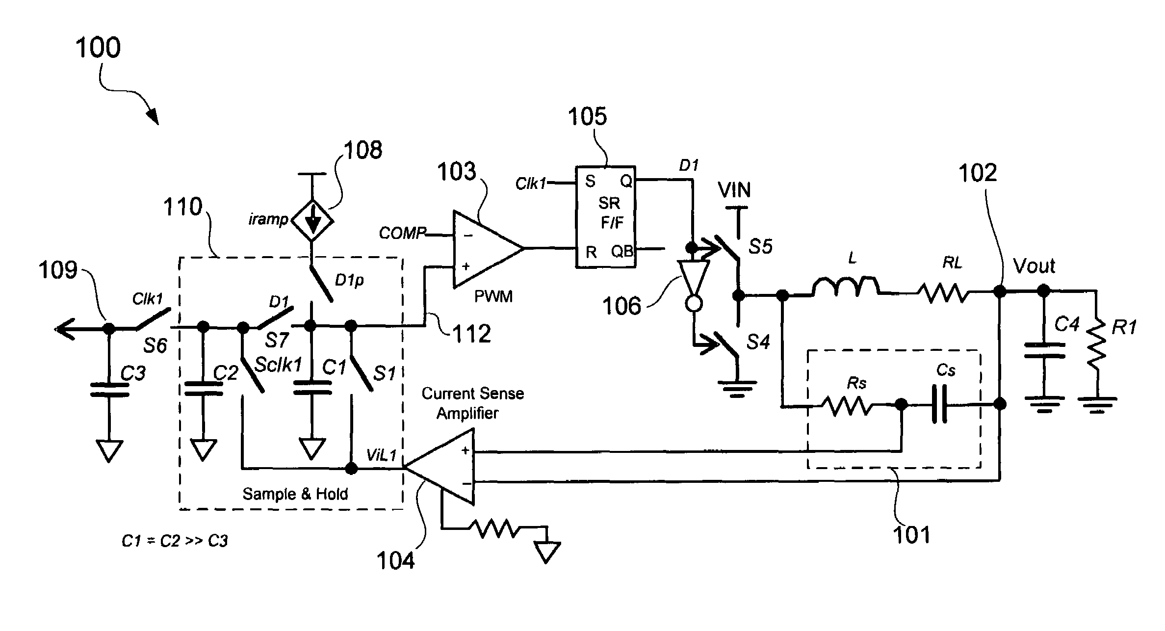
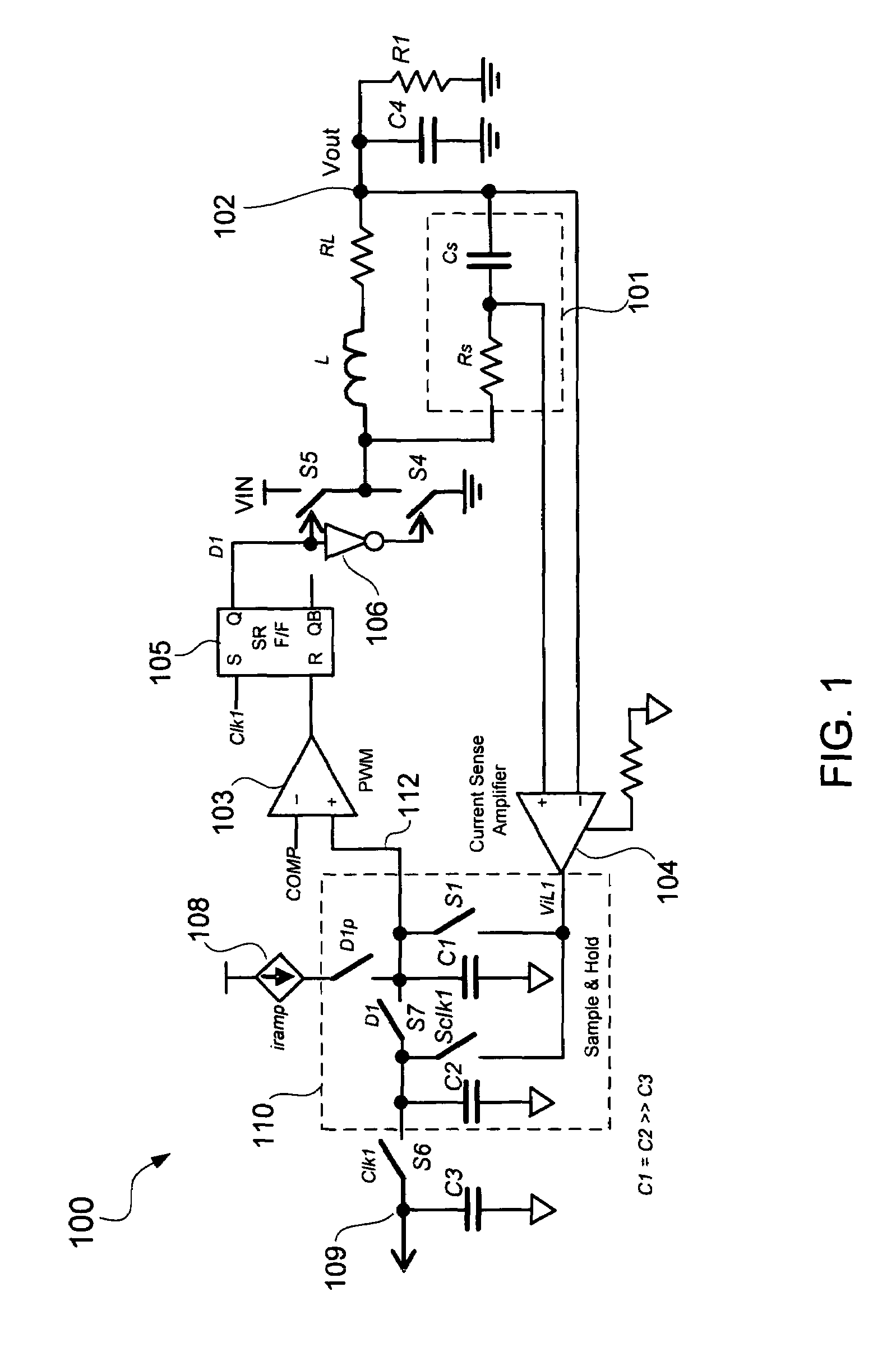
[0015]FIG. 1 schematically shows the use of a sample and hold inductor current sense configuration in a voltage regulator in accordance with an embodiment of the present invention. In the example of FIG. 1, the inductor current sense configuration is employed in a low voltage, high current voltage regulator circuit 100. The regulator circuit 100 may have multiple phases but circuitry for only one phase is shown in FIG. 1 for clarity of illustration. The inductor current sense configuration may also be employed in other voltage regulators wit...


PUM


Abstract

A sample and hold inductor current sense configuration senses inductor current flowing through an output inductor of a voltage regulator and generates an average of the sensed inductor current. The average of the sensed inductor current may be generated from samples of peaks and valleys of the sensed inductor current. For example, the peak of the sensed inductor current may be stored in a first capacitor and the valley of the sensed inductor current may be stored in a second capacitor. The first and second capacitors may be coupled together to generate the average of the sensed inductor current. The average of the sensed inductor current may be provided to a droop control circuit to control droop of an output voltage of the voltage regulator. An input offset voltage of a current sense amplifier sensing the inductor current may be calibrated between samplings of the sensed inductor current.

Description

BACKGROUND OF THE INVENTION[0001]1. Field of the Invention[0002]The present invention relates generally to electrical circuits, and more particularly but not exclusively to voltage regulators.[0003]2. Description of the Background Art[0004]A voltage regulator generates a regulated output voltage VOUT from an input voltage VIN. Ideally, the voltage regulator maintains the output voltage VOUT within regulation despite varying load current. However, this is not always the case in real world conditions. The output voltage VOUT of a practical voltage regulator may droop, i.e., decrease linearly, with changing load current. Droop control circuits have been developed to control output voltage droop. However, a droop control circuit must be able to accurately detect load current in order to control droop voltage.[0005]The present disclosure pertains to detecting the average of sensed inductor current, which may be used for droop control and other voltage regulator applications.SUMMARY[0006]...

Claims


Application Information

Patent Timeline
Patent Type & Authority Patents(United States)
IPC IPC(8): G05F1/613G05F1/00
CPCG01R19/003H02M3/156H02M2001/0009H02M1/0009
Inventor GUO, YIGANG
Owner SEMICON COMPONENTS IND LLC
Why Eureka
Try Eureka