Flame detection device and method of detecting flame

a detection device and flame detection technology, applied in fire alarms, combustion processes, lighting and heating apparatus, etc., can solve problems such as potential danger, conventional devices do not have the ability to sense multiple fuels,

Active Publication Date: 2010-05-04
FOSSIL POWER SYST
View PDF6 Cites 34 Cited by
  • Summary
  • Abstract
  • Description
  • Claims
  • Application Information

AI Technical Summary

Benefits of technology

[0010]An object of the present invention is thus to provide an improved device for detecting flame in furnace and boiler systems, such as a multi-burner system in a combustion unit.
[0016]The statistical recognition routine may include analysis of the spatial, temporal and energy features of the burner flame thereby providing a confidence level, indicating the likelihood of flame presence. The analysis may be updated continuously at predetermined time intervals to effectively provide a moving time-window of a predetermined length over which confidence level is accumulated.

Problems solved by technology

In the event of a flame failure, a burner may continue to supply fuel resulting in a potentially hazardous situation.
This is a common problem, since conventional detectors have difficulty with flame discrimination under these circumstances.
However, the sensor used in this method is a single discrete element, and only allows for the overall light intensity to be detected in a defined spatial region.
Additionally, such conventional devices do not have the ability to sense multiple fuels due to spectral wavelength limitations of the individual sensors.

Method used


Image

  • Flame detection device and method of detecting flame
  • Flame detection device and method of detecting flame
  • Flame detection device and method of detecting flame

Examples


Embodiment Construction

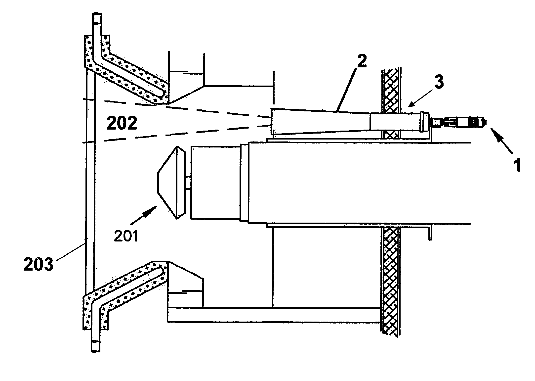
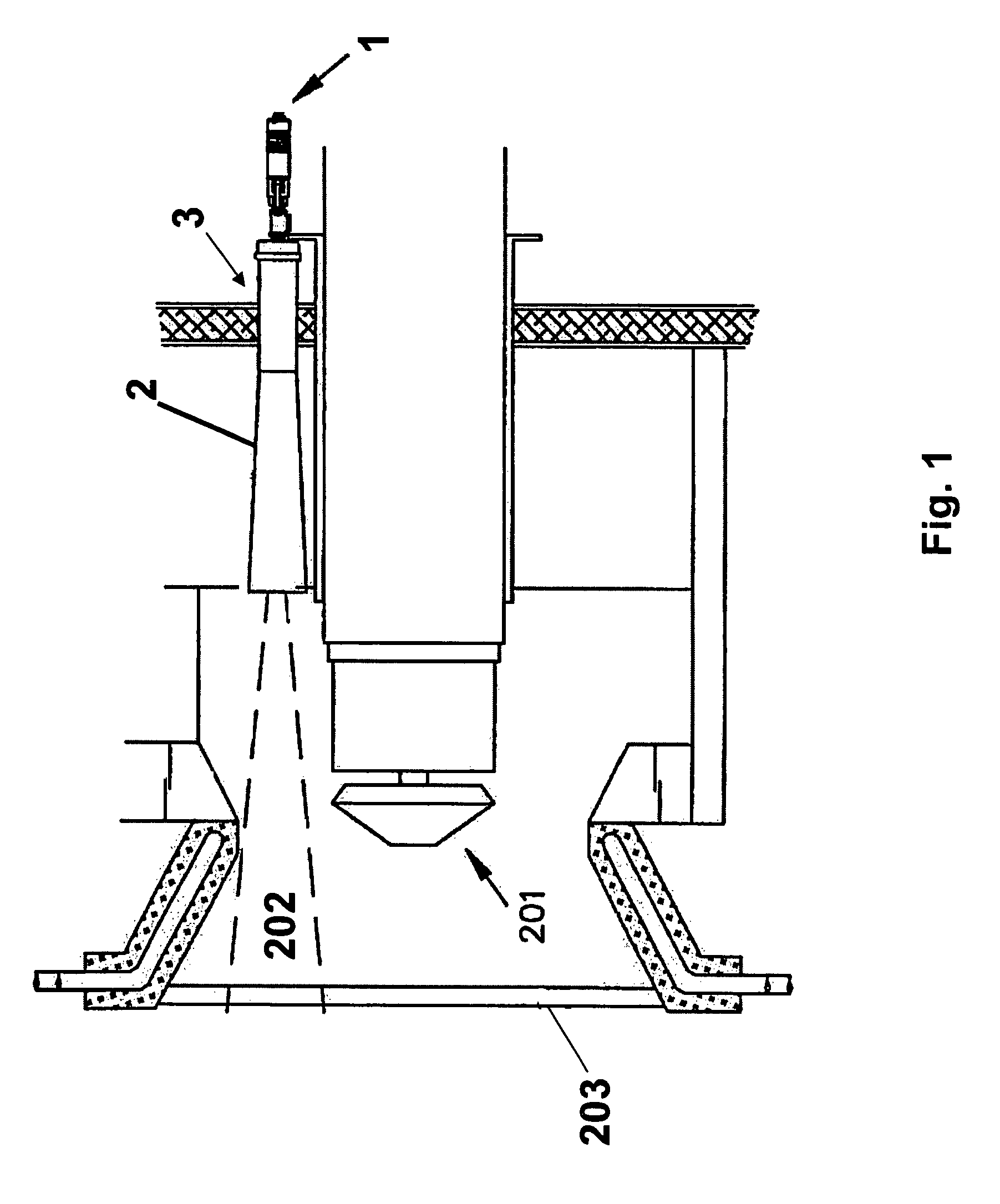
[0028]As illustrated in FIG. 1, a flame detection device 1 is positioned at a proximal end of a sighting tube 2. The sighting tube 2 and its associated viewing optics are constructed using conventional methods, for instance, according to the disclosure of U.S. Pat. No. 5,107,128. As illustrated, the sighting tube 2 is positioned within a burner viewing port 3 of a boiler furnace, such that the distal end of the sighting tube 2 is in the vicinity of a flame spot 202 associated with a burner 201. For simplicity in illustration, a single burner 201 is shown in FIG. 1. However, the flame detection device of the present invention may be employed in multiple burner systems as well.

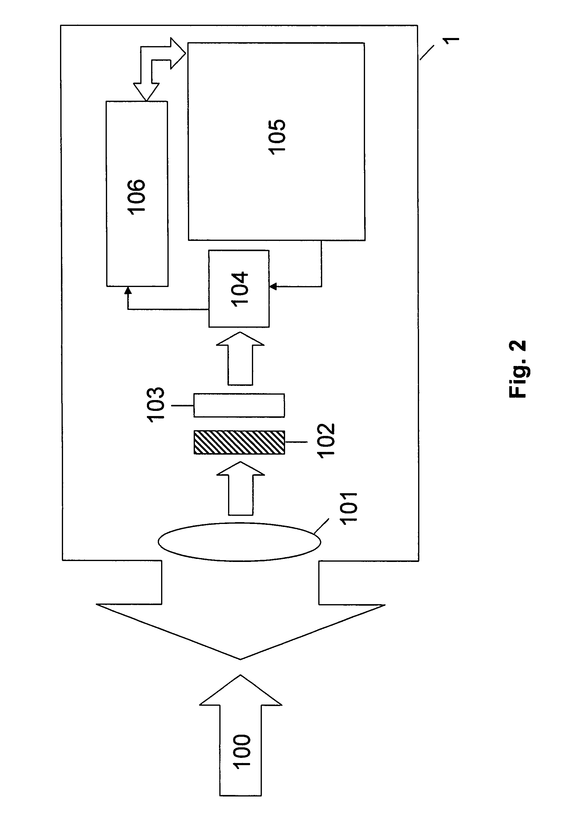
[0029]An exemplary embodiment of the flame detection device 1 according to the present invention will now be described in detail with reference to FIG. 2. The incident flame 100 represents the flame spot 202 (as viewed through the sighting tube 2 shown in FIG. 1) in the line of sight of the flame detection devic...


PUM


Abstract

A device and method for detecting flame using real-time continuous imaging and pattern recognition of infrared (IR) images of a flame region. Infrared emissions radiated from the region pass through a wide field-of-view lens and are detected by a Charged-Coupled Device (CCD) array sensitive to the near IR range. The system then digitizes the image, extracts characteristic parameters from the measurement and stores both the image and characteristic information for pattern recognition. To accomplish the pattern recognition function, the derived real-time characteristics of the current measurement are statistically compared to pre-stored patterns representative of images of radiation emitted from the region while known flame conditions prevail within the region. Based on this comparison, an assessment is made to determine the presence or absence of flame. The characteristic measurements are also used for evaluating the quality of flame.

Description

[0001]This application is a U.S. utility application claiming priority to U.S. Provisional Application No. 60 / 799,666 filed 12 May 2006, the entire content of which is incorporated herein by reference.FIELD OF INVENTION[0002]The present invention relates to a device and a method for detecting flame in furnace and burner systems. In particular, the present invention relates to a device and a method designed to digitally monitor, in real time, the presence or absence of flame in commercial and industrial furnaces.BACKGROUND OF THE INVENTION[0003]Multiple burners are widely employed in industrial boilers, such as those used in conjunction with steam turbines for electric power generation. These burners may be fired by a variety of fuels such as coal, oil or gas and usually have an associated supporting igniter for initial combustion of the fuel. It is necessary to monitor the flame on these burners to ensure that flame is present at all times during the operation of the burner. In the ...

Claims


Application Information

Patent Timeline
Patent Type & Authority Patents(United States)
IPC IPC(8): G08B17/12
CPCF23N5/082F23N2029/20F23N2229/20
Inventor MCLELLAN, DOUGLAS
Owner FOSSIL POWER SYST
Why Eureka
Try Eureka