Electroimpedance tomograph

a tomograph and electromagnetic technology, applied in the field of electromagnetic tomographs, can solve the problems of electromagnetic interference, unsuitable for routine surgery in medicine, and the change of the dominant frequency of electromagnetic interference,

Active Publication Date: 2010-05-04
DRAGERWERK AG
View PDF14 Cites 12 Cited by
  • Summary
  • Abstract
  • Description
  • Claims
  • Application Information

AI Technical Summary

Benefits of technology

[0009]The object of the present invention is to provide an EIT that is extensively insensitive to electromagnetic background signals without requiring the intervention of a human operator.
[0018]Due to the EIT, according to the present invention, no additional external apparatus or instruments need advantageously to be used in order to detect background signals. The electrodes themselves are used, instead, as an “antenna,” and the background signals are processed, except for a narrow-band evaluation, in exactly the same manner by the electronic circuits and the control unit, so that the background signals are obtained, thus detected and processed, in such a way as if they were superimposed to the useful signals during the actual measuring operation of the EIT. Due to the transformation of the time course of a time period of the background into a frequency spectrum, it is possible to search for ranges in which the power of the background is sufficiently low, so that a useful signal to background signal ratio above a preset threshold value can be obtained.

Problems solved by technology

This procedure is sufficient for laboratory applications, but is unsuitable for the routine operation in medicine, e.g., in intensive care units.
Such interfering signals may be caused, for example, by monitors in the environment (ECG, etc.) or other medical apparatus; when other apparatus are switched on at not too great a distance from the EIT, the electromagnetic interferences, and especially the dominant frequencies of these interferences may change.

Method used


Image

  • Electroimpedance tomograph
  • Electroimpedance tomograph
  • Electroimpedance tomograph

Examples


Embodiment Construction

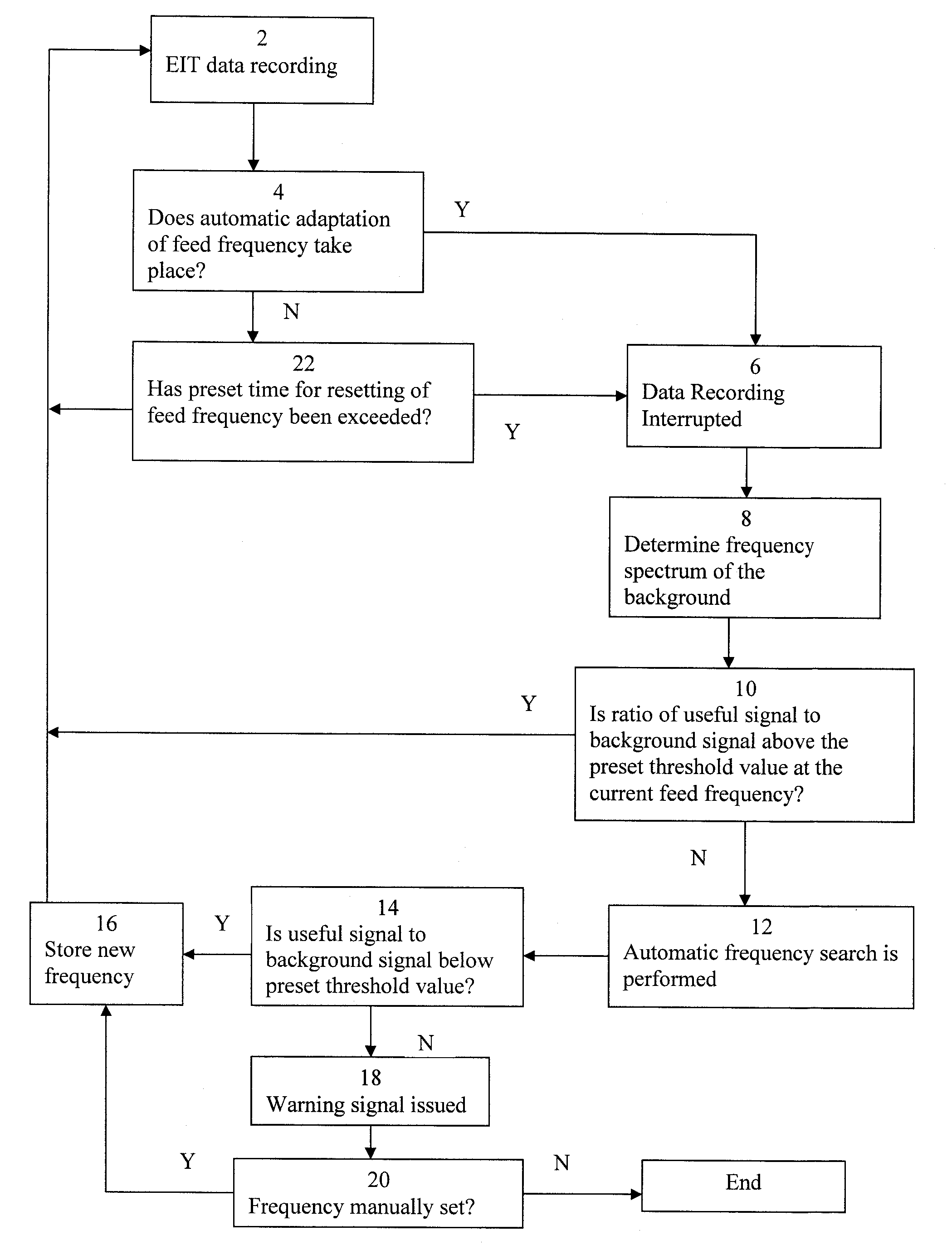
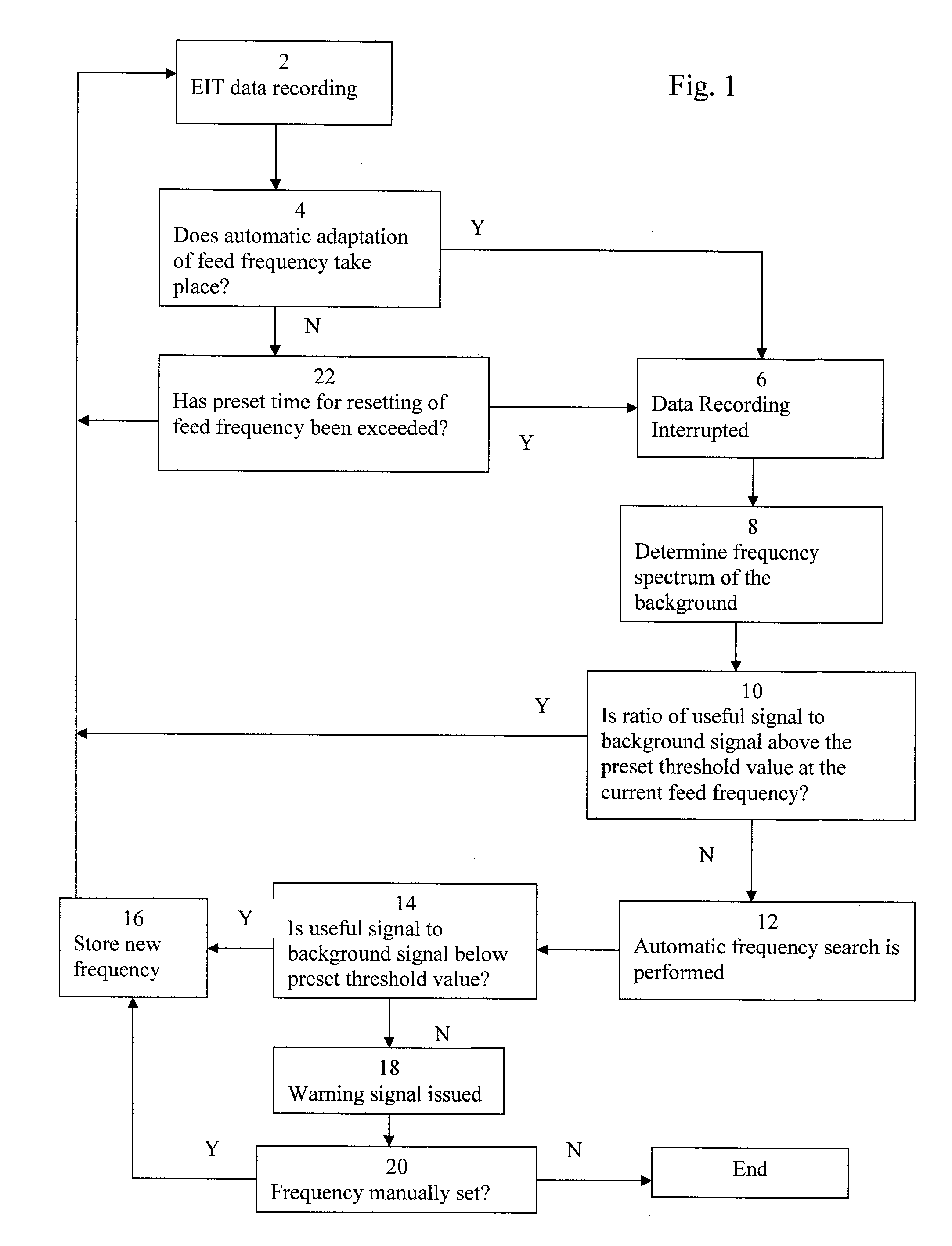
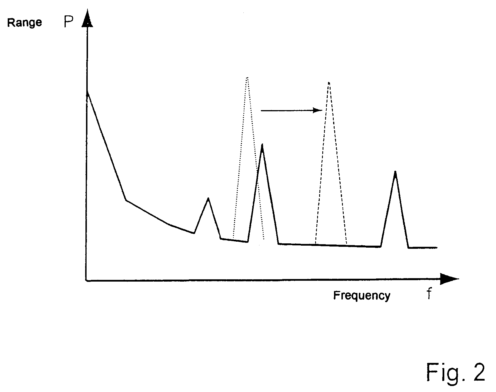
[0024]Provisions are made in a preferred embodiment of the EIT with automatic setting of the current feed frequency for the voltage time series to take place for the determination of the background without current feed, i.e., the EIT records the background due to electromagnetic disturbing interfering signals without any superimposition of useful signals. The voltages occurring at the electrodes pass through the analog and digital electric circuits as in the case of normal operation. After digitization of the data with a suitable sampling frequency, a frequency spectrum is determined from the voltage time series in the digital form (by Fourier transformation). The change in the sampling frequency permits, moreover, access to other frequency ranges and / or a change in the lengths of the time periods to be analyzed, which can improve the accuracy of the spectrum. A background frequency spectrum is shown, for example, in FIG. 2. The background spectrum is shown by solid line and it show...


PUM

PropertyMeasurementUnit
voltageaaaaaaaaaa
impedance distributionaaaaaaaaaa
frequencyaaaaaaaaaa

Abstract

An electroimpedance tomograph including a plurality of electrodes placed on a body, measuring circuits processing voltage signals recorded by the electrodes, and a control unit supplying two electrodes each with an alternating current. The control unit has a preset feed frequency. The control unit processes the processed voltage signals of all other electrodes to reconstruct the impedance distribution of the body in the electrode plane. The control unit provides for an automatic setting of the current feed frequency / frequencies to record a background frequency spectrum by detecting the electrode voltage signals over a preset period of time and record them as a voltage time series and transform them into a frequency spectrum. The control unit searches in the background frequency spectrum for a frequency (different states) or frequencies (different frequencies) that leads to a useful signal to background ratio above a preset threshold value when used as a feed frequency.

Description

CROSS REFERENCE TO RELATED APPLICATIONS[0001]This application claims the benefit of priority under 35 U.S.C. § 119 of German patent application DE 103 39 084.7 filed Aug. 26, 2003 the entire contents of which are incorporated herein by reference.FIELD OF THE INVENTION[0002]The present invention pertains to an electroimpedance tomograph with a plurality of electrodes that can be placed on the body, electronic circuits that process the voltage signals recorded by the electrodes, and a control unit, which is set up to supply two, preferably adjacent electrodes each with an alternating current, which has a preset feed frequency in case of measurements performed in different states and different preset feed frequencies in case of measurements performed at different frequencies, and to process the processed voltage signals of all other electrodes in order to reconstruct the impedance distribution of the body in the electrode plane from them.BACKGROUND OF THE INVENTION[0003]Such an electro...

Claims


Application Information

Patent Timeline
Patent Type & Authority Patents(United States)
IPC IPC(8): A61B5/05A61B5/053G01N27/02
CPCA61B5/0536Y10S128/908
Inventor GARBER, YVOSTEEGER, MARKUSLI, JIANHUALEONHARDT, STEFFENRUTERBORIES, JANGOLDAU, RAINER
Owner DRAGERWERK AG
Why Eureka
Try Eureka