Supercharge Your Innovation With Domain-Expert AI Agents!

Bus control apparatus and bus control method

a bus control and bus protocol technology, applied in the direction of digital storage, instruments, electric digital data processing, etc., can solve the problems of inability to retrieve correct read data, and complex implementation of bus protocol-based methods. implementation of non-posted write is more complex than that of posted wri

Active Publication Date: 2010-05-04
KK TOSHIBA
View PDF13 Cites 0 Cited by
  • Summary
  • Abstract
  • Description
  • Claims
  • Application Information

AI Technical Summary

Benefits of technology

The present invention provides a bus control apparatus that can prevent data from being written to memory when a read command signal is detected. This prevents data from being lost or corrupted during power failures or other system crashes. The apparatus includes a block that outputs a write command signal and a bus connection control unit that monitors the signals on the bus. When a read command signal is detected, the control unit blocks the connection between the block and the bus, outputs a dummy read command signal, and releases the blockage when a response signal is received. This prevents data from being written to memory when it is not needed, which improves the reliability and efficiency of the system.

Problems solved by technology

It is a problem of memory consistency or coherency, which means correct read data cannot be retrieved unless reading by the other block B is carried out after the posted write reaches the shared memory.
However, a bus protocol-based method has a problem of involving complex HW implementation for executing the protocol.
In general, implementation of non-posted write is more complex than that of posted write.
In addition, performance of HW, especially throughput and overhead in terms of operating frequency, may present a problem.
However, a problem with methods based on HW implementation is that HW implementation is complex.
Therefore, application of address interlocking in every transaction can present a problem in terms of performance, especially throughput and operating frequency.
However, methods based on software implementation generally have a problem of processing being sometimes extremely complex.
Because of this fact, when a vendor supplying SoC chips leaves software implementation to a customer, for example, the customer might not be able to accept software implementation that involves such complex processing.

Method used


Image

  • Bus control apparatus and bus control method
  • Bus control apparatus and bus control method
  • Bus control apparatus and bus control method

Examples


Embodiment Construction

[0030]An embodiment of the invention will be described with reference to the drawings.

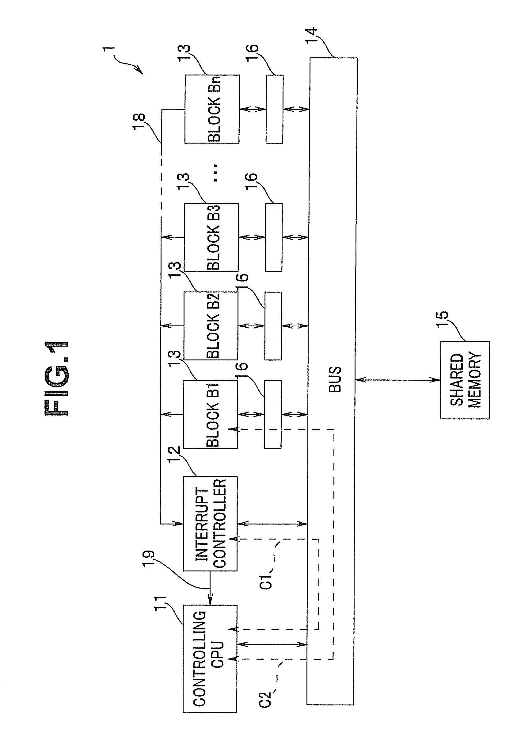
[0031]First, with respect to FIG. 1, a configuration of a bus control apparatus according to the present embodiment will be described. FIG. 1 is a block diagram showing the configuration of the bus control apparatus according to the present embodiment.

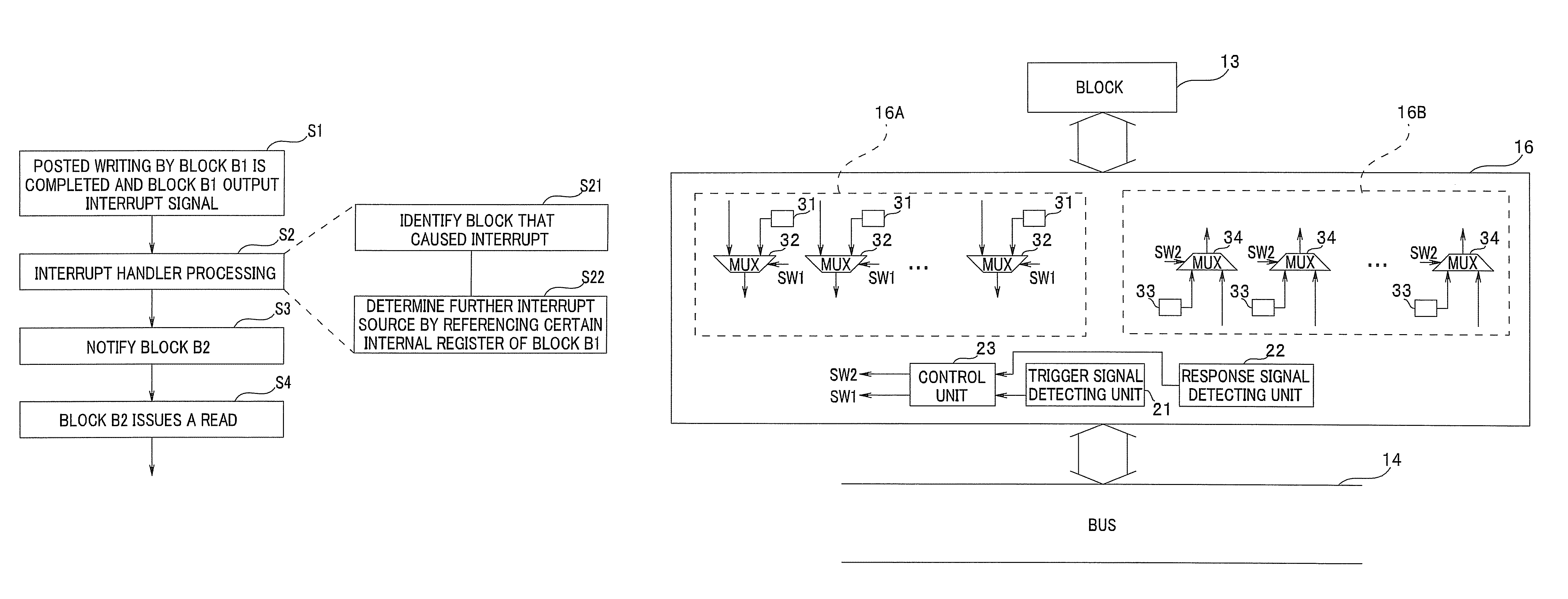
[0032]As shown in FIG. 1, a bus control apparatus 1 includes a central processing unit (hereinafter called a “controlling CPU”) 11 for bus control, an interrupt controller 12, a plurality of blocks 13 which are functional blocks each performing predetermined processing, a bus 14 as a system bus, shared memory 15, and a bus connection control unit 16 provided between each of the blocks 13 and the bus 14. There are n blocks 13 (n being a positive integer), each connected to the bus 14 via the bus connection control unit 16. The bus control apparatus 1 of FIG. 1 is formed as a semiconductor circuit on a semiconductor chip as a semiconductor device, for e...


PUM


Abstract

A bus control apparatus includes a plurality of blocks configured to output a write command for writing data into memory via a bus, and a bus connection control unit provided in correspondence with each of the blocks. The bus connection control unit monitors signals between the bus and the block, and upon detecting a read command signal for reading data in a cause register of the block, blocks connection of a signal line between the block and the bus and outputs a dummy read command signal for the memory. The bus connection control unit releases blockage when a response signal for the dummy read command signal is received.

Description

CROSS REFERENCE TO RELATED APPLICATION[0001]This application is based upon and claims the benefit of priority from the prior Japanese Patent Application No. 2007-108394 filed on Apr. 17, 2007; the entire contents of which are incorporated herein by this reference.BACKGROUND OF THE INVENTION[0002]1. Field of the Invention[0003]The present invention relates to a bus control apparatus and a bus control method, and more particularly, to a bus control apparatus including one or more blocks configured to output a write command signal for writing data into memory via a bus, and a bus control method.[0004]2. Description of the Related Art[0005]There have been known apparatuses in which data is transmitted / received between functional blocks via a bus. For example, in recent apparatuses, a number of blocks on a System-on-Chip (SoC) transmit / receive data to and from each other by way of a system bus and via shared memory that is connected to the chip.[0006]By way of example, when a block A is ...

Claims


Application Information

Patent Timeline
Patent Type & Authority Patents(United States)
IPC IPC(8): G06F13/14G06F13/24
CPCG06F13/28
Inventor HATAKEYAMA, TSUTOMU
Owner KK TOSHIBA
Features
  • R&D
  • Intellectual Property
  • Life Sciences
  • Materials
  • Tech Scout
  • Unparalleled Data Quality
  • Higher Quality Content
  • 60% Fewer Hallucinations
Learn More