Multi-fuel multi-injection system for an internal combustion engine

a multi-fuel injection and internal combustion engine technology, applied in the field of internal combustion engines, can solve the problems of inability to meet the needs of combustion engines, slow response time, inaccurate temperature regulation, etc., and achieve the effect of maximizing efficiency and minimizing emissions and knocks

Inactive Publication Date: 2010-05-11
MICHIGAN MOTOR TECH LLC
View PDF23 Cites 32 Cited by
  • Summary
  • Abstract
  • Description
  • Claims
  • Application Information

AI Technical Summary

Problems solved by technology

For engines operating without a conventional spark ignition, commonly known as the homogenous charge compression ignition (HCCI) mode, the main challenge is to maintain a stable start of combustion (SOC) when the engine is operated at steady state and transient conditions.
The instability of the SOC is mainly due to difficulties in the control of in-cylinder air-to-fuel mixture temperature on a cycle-to-cycle basis.
However, a disadvantage of using the intake heater is its slow response time caused by a large time constant of the heater and a transportation delay from the heater to the cylinder.
The slow response time results in inaccurate temperature regulation during the transient operation of the engine.
However, a rate of in-cylinder residual exhaust gas is uncontrollable, leading to SOC and indicated mean effective pressure (IMEP) variation.
However, the prior art dual-injection dual-fuel system is limited to injecting gasoline into an intake port of the engine.

Method used


Image

  • Multi-fuel multi-injection system for an internal combustion engine
  • Multi-fuel multi-injection system for an internal combustion engine
  • Multi-fuel multi-injection system for an internal combustion engine

Examples


Embodiment Construction

[0017]The following detailed description and appended drawings describe and illustrate various embodiments of the invention. The description and drawings serve to enable one skilled in the art to make and use the invention, and are not intended to limit the scope of the invention in any manner.

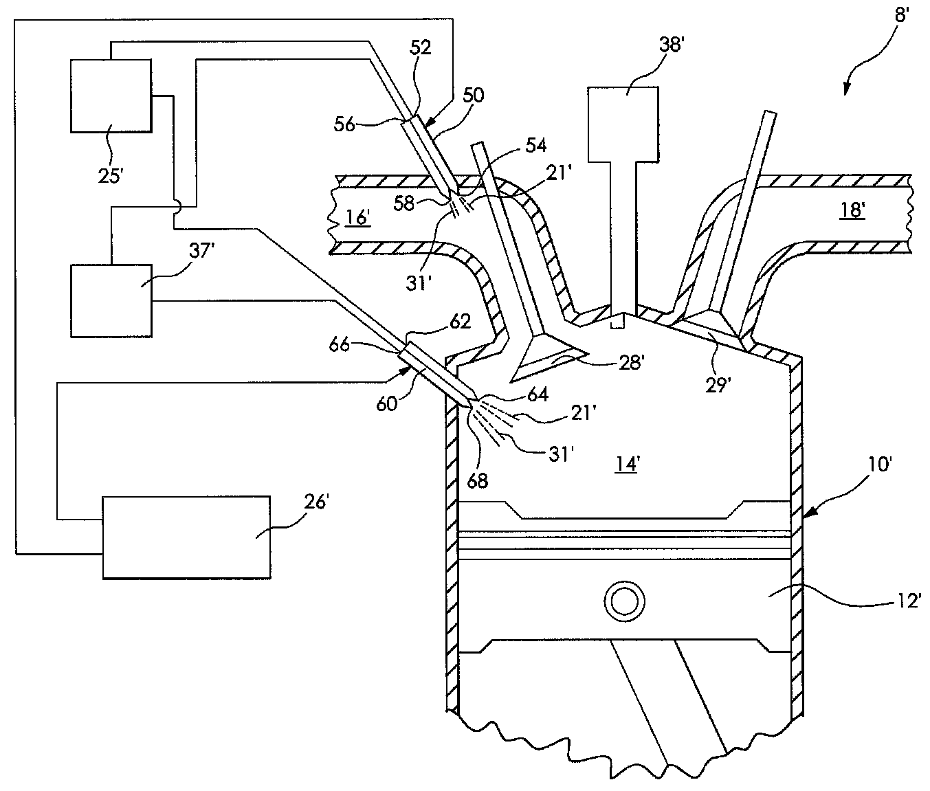
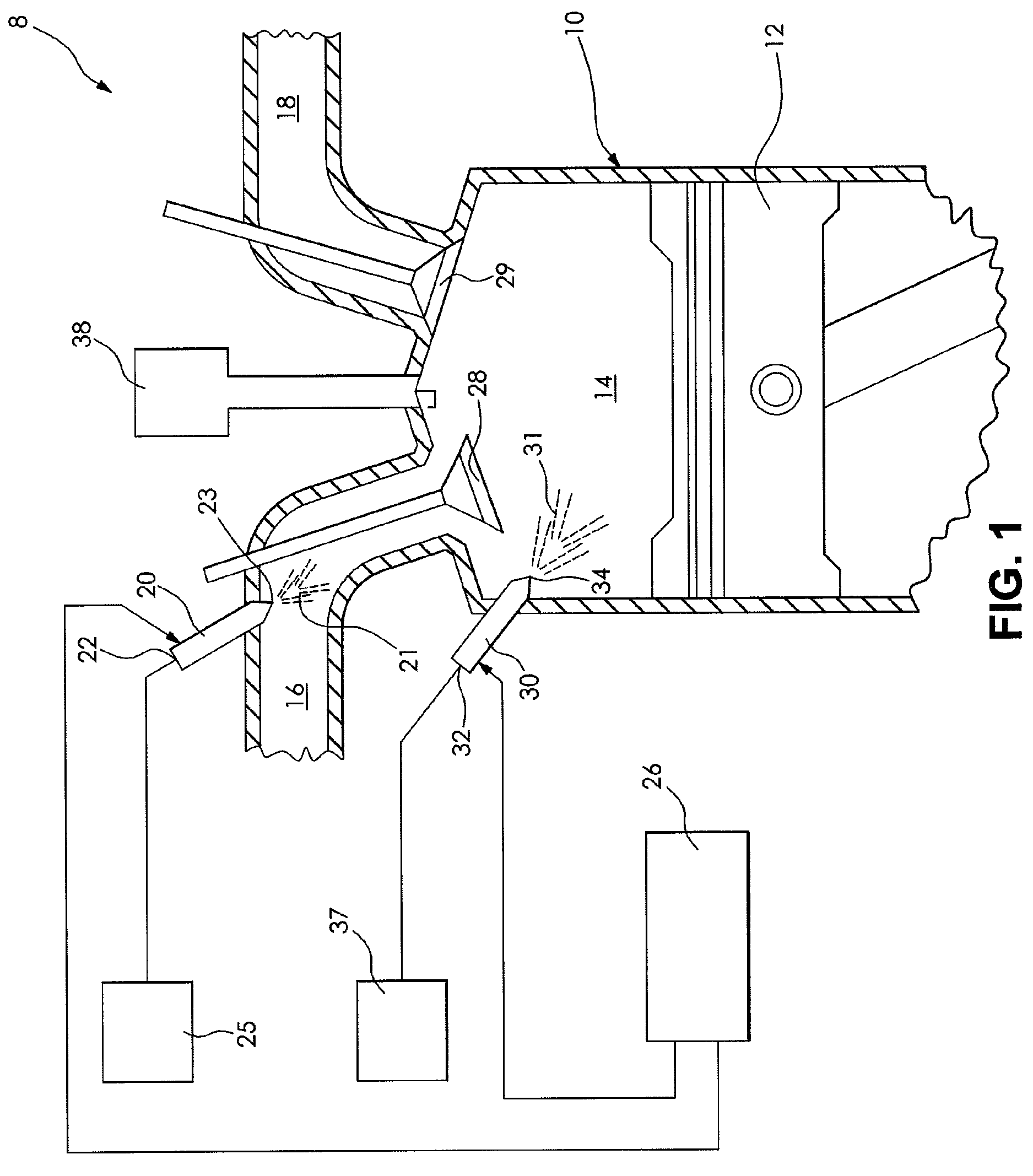
[0018]FIG. 1 shows an injection system 8 for a cylinder 10 of an internal combustion engine according to an embodiment of the invention. It is understood that the internal combustion engine can have additional cylinders as desired. The cylinder 10 has a hollow interior with a piston 12 slideably disposed therein. The piston 12 and a wall of the cylinder 10 cooperate to define a combustion chamber 14 therebetween. The cylinder 10 includes an intake path 16 and an exhaust path 18. It is understood that the cylinder can include additional intake paths and exhaust paths if desired.

[0019]In the embodiment shown, the intake path 16 of the cylinder 10 includes a first injector 20. The first injector ...


PUM


Abstract

A fuel injection system for an internal combustion engine is disclosed, the fuel injection system including a plurality of injectors, wherein each of the injectors is adapted to inject at least one of an alternative fuel and a fossil fuel over a full range of operating conditions of the engine.

Description

FIELD OF THE INVENTION[0001]The invention relates to an internal combustion engine, and more particularly to a multi-fuel multi-injection system for an internal combustion engine which is capable of injecting a fossil fuel and an alternative fuel over a full range of operating conditions of the engine.BACKGROUND OF THE INVENTION[0002]The automotive industry is continually researching the combustion process of an internal combustion engine to improve a fuel economy and emissions thereof. To optimize performance of the engine, it is important to be able to control the engine on a cycle-to-cycle basis. For engines operating without a conventional spark ignition, commonly known as the homogenous charge compression ignition (HCCI) mode, the main challenge is to maintain a stable start of combustion (SOC) when the engine is operated at steady state and transient conditions. The instability of the SOC is mainly due to difficulties in the control of in-cylinder air-to-fuel mixture temperatu...

Claims


Application Information

Patent Timeline
Patent Type & Authority Patents(United States)
IPC IPC(8): F02B7/00F02B7/06
CPCF02B17/005F02D19/0692F02D19/081F02M43/04F02M69/044F02M69/045F02D19/061F02D19/0689F02B2023/102F02B2275/16F02D19/0647Y02T10/36Y02T10/123F02D19/0655F02B23/101Y02T10/12Y02T10/30
Inventor HUNG, DAVID LING-SHUNZHU, GEORGE GUOMING
Owner MICHIGAN MOTOR TECH LLC
Why Eureka
Try Eureka