Arrowhead with unfolding blades

a technology of arrowheads and blades, applied in the field of arrowheads, can solve the problems of unable to fend for itself, prolonged suffering, and relative rapid death via blood loss, and achieve the effect of expanding the size of the entry wound and maximizing the debilitating trauma

Inactive Publication Date: 2010-05-11
TENTLER LYNN A
View PDF56 Cites 61 Cited by
  • Summary
  • Abstract
  • Description
  • Claims
  • Application Information

AI Technical Summary

Benefits of technology

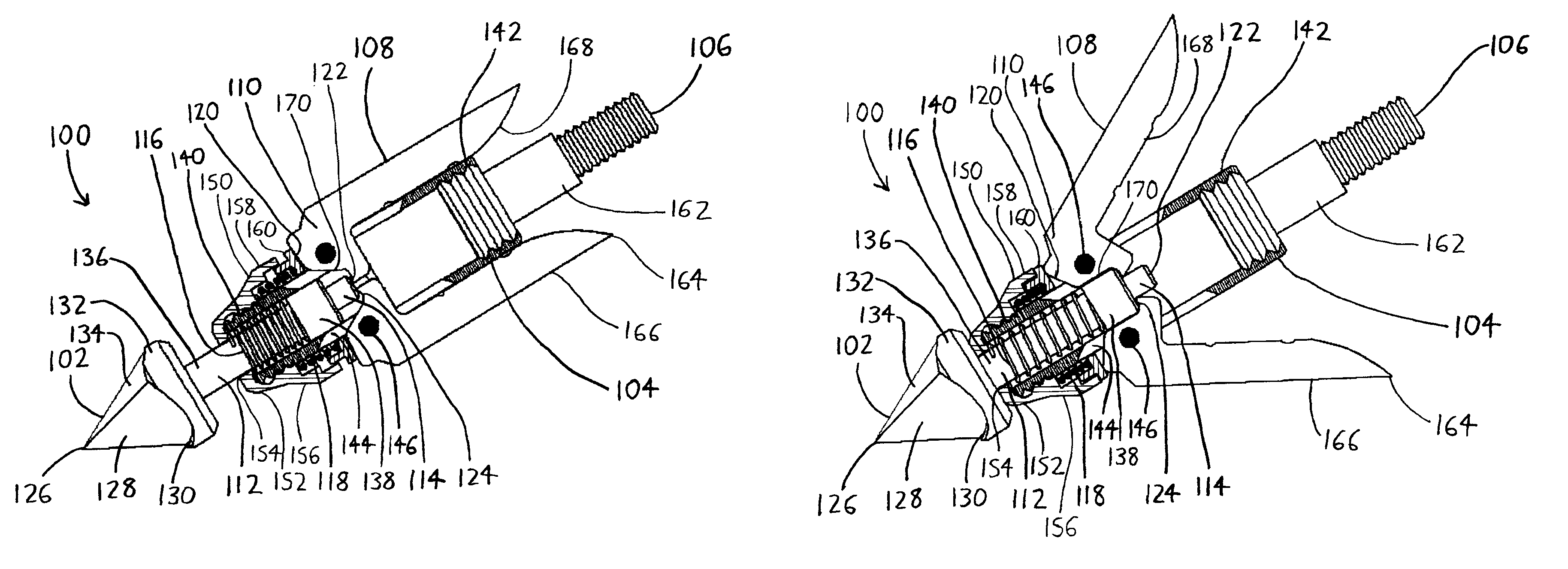
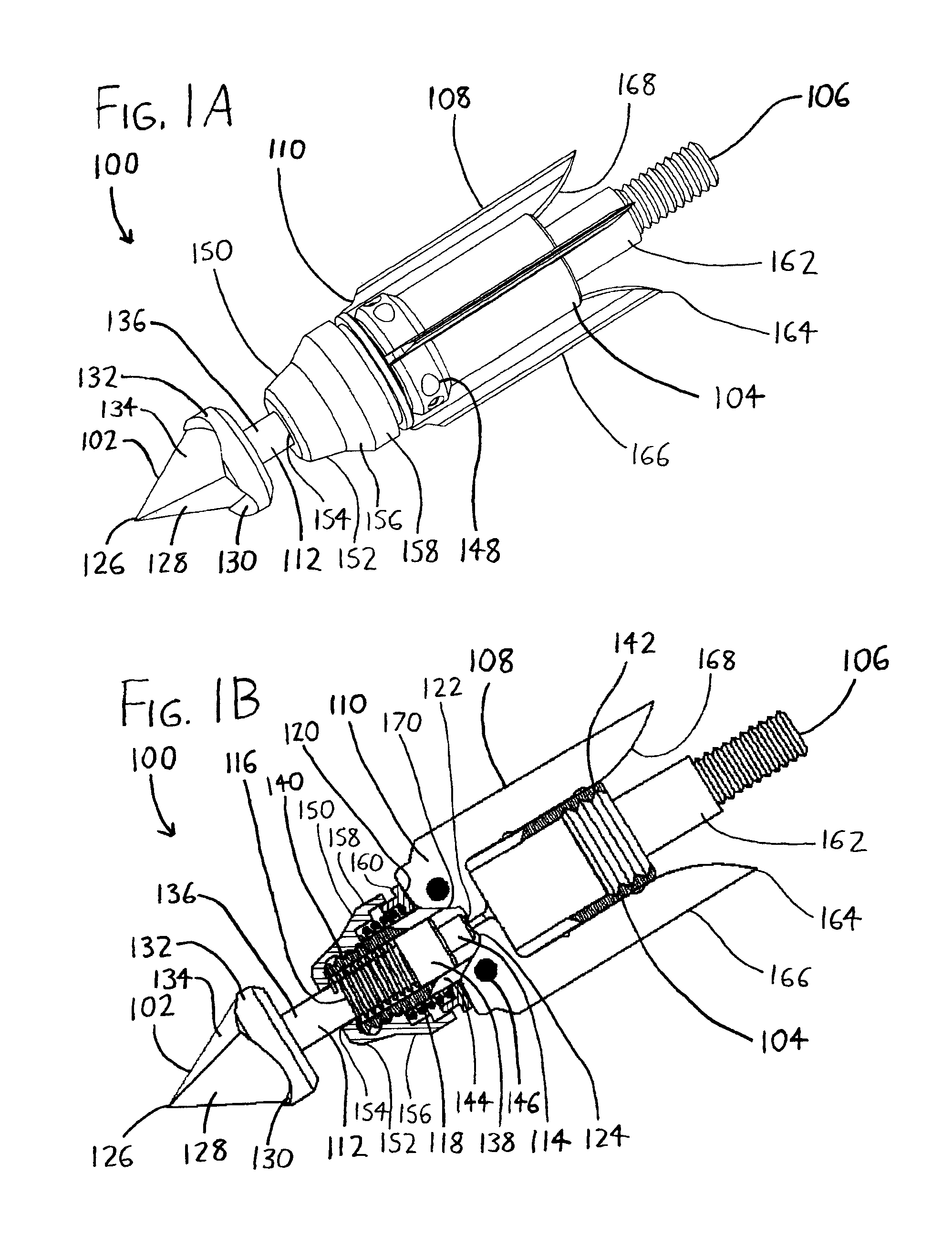
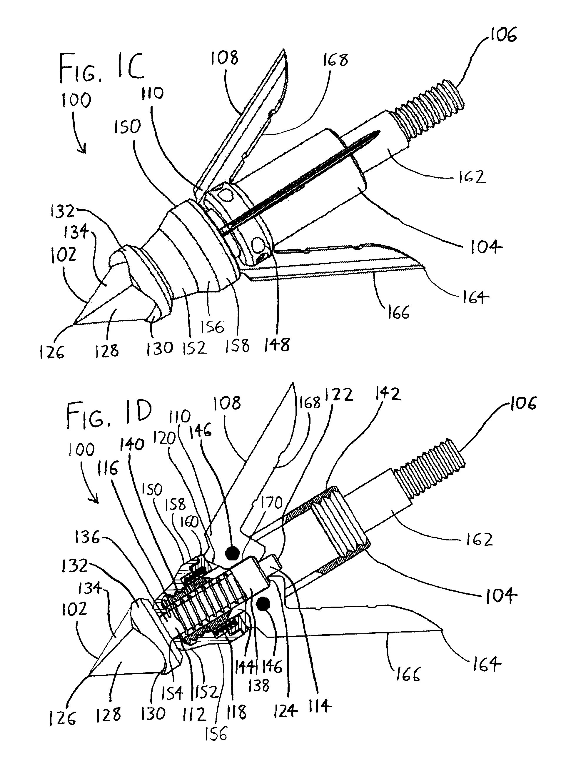
[0013]Referring to the exemplary arrowhead depicted in FIGS. 1A-1D at the reference numeral 100, the arrowhead 100 includes a tip 102, a body 104 extending rearwardly from the tip 102 and terminating in a tail end 106 adapted to mount to an arrow shaft (such a shaft not being shown), and one or more blades 108 on the body 104 which each have a pivot end 110 about which the blade 108 pivots with respect to the body 104. Here, the arrowhead 100 is shown with three blades 108, though more or less are possible. Each blade 108 is then pivotable about its pivot end 110 between an open state wherein the blade 108 is folded outwardly from the body 104 (see FIGS. 1C-1D) and a closed state wherein the blade 108 is folded inwardly to rest closer to the body 104 (see FIGS. 1A-1B). As best seen in FIGS. 1B and 1D, an actuating member 112—here provided in the form of a shaft with a protruding nub 114 of lesser diameter, though the actuating member 112 might take other forms—extends rearwardly from the tip 102, and into the interior of the body 104. This actuating member 112 is movable within and along the length of the body 104 such that it may travel rearwardly from the position shown in FIGS. 1A-1B—wherein the tip 102 and actuating member 112 are in an extended in-flight position, prior to impact with a target—to the position shown in FIGS. 1C-1D, wherein the tip 102 (and thus the actuating member 112) is urged rearwardly within the body 104 upon the impact of the tip 102 with a target. As best seen from a comparison of FIGS. 1B and 1D, when the actuating member 112 is urged rearwardly into the interior of the body 104, it urges against the blade pivot ends 110 to move the blades 108 from their closed state (FIG. 1B) to their open state (FIG. 1D), and thus the blades 108 unfold in the moment after the impact of the tip 102 to increase the cutting area of the arrowhead 100.
[0014]First and second springs 116 and 118 are seen in FIGS. 1B and 1D, wherein only the cross-section of the second spring 118 is visible. The second spring 118 acts as a latching spring when the arrowhead 100 is in its in-flight closed state (FIGS. 1A-1B), biasing the blades 108 with respect to the body 104 to urge the blades 108 toward the closed state. More particularly, the latching spring 118 acts against a camming surface 120 on the pivot end 110 of each blade 108, wherein the camming surface 120 is contoured to store energy within the second / latching spring 118 when the blade 108 is in the open state, and to relieve energy stored within the second / latching spring 118 when the blade 108 is in the closed state. The latching spring 118 thereby attempts to close the blades 108. In contrast, the first spring 116 constantly biases the actuating member 112 rearwardly with respect to the body 104 to urge the actuating member 112 rearwardly into the interior of the body 104, and therefore against the pivot ends 110 of the blades 108, to urge the blades 108 toward the open state. However, the first spring 116—which may be regarded as a blade opening spring—is defeated by the action of the latching spring 118 until the actuating member 112 begins to move rearwardly owing to impact forces on the tip 102, at which point the opening spring 116 assists the actuating member 112 in defeating the latching spring 118 and opening the blades 108. The opening spring 116 therefore plays only a minor role in opening the blades 108, but it is nonetheless useful in maintaining the actuating member 112 against the pivot ends 110 of the blades 108 when the blades 108 are in their closed state (see FIG. 1B), and preventing the actuating member 112 from sliding forwardly within the body 104 and out of contact with the blade pivot ends 110.
[0017]The foregoing arrangement is preferably used in conjunction with a preferred tip structure, exemplified in FIGS. 1A-1D. The tip 102 extends rearwardly from a leading edge 126, and includes one or more penetrating surfaces 128 which slope outwardly with respect to the axis of the tip 102 as these penetrating surfaces 128 extend rearwardly. The leading edge 126 and penetrating surfaces 128 are intended to initiate and expand an entry wound as the tip 102 penetrates target game. One or more collecting surfaces 130 are then provided which are forwardly exposed on the tip 102 (i.e., at least a portion of the collecting surfaces 130 is situated such that it will directly impact the tissue of the target game about the entry wound during entry), with these collecting surfaces 130 being oriented at least substantially perpendicular to the axis of the tip 102, and / or being concave with respect to a plane perpendicular to the axis of the tip 102. In FIGS. 1A-1D, these collecting surfaces 130 are provided by concave areas defined between the outer perimeter of a cylindrical tip base 132 and a tetrahedral tip head 134. These collecting surfaces 130 are intended to collect tissue, such that tissue “piles up” behind the collecting surfaces 130 during entry, and so that the collecting surfaces 130 move the tissue forwardly in front of the tip 102 such that an entry wound cannot easily reclose. This effect expands the size of the entry wound, and also helps to generate sufficient rearward force on the actuating member 112 that it almost immediately actuates the blades 108 into their open state upon tip impact (more specifically upon impact of the collecting surfaces 130). The collecting surfaces 130 thereby help to fully open the blades 108 before they enter the target game rather than thereafter, and thereby maximize debilitating trauma.

Problems solved by technology

In those cases where the first shot does not immediately critically wound and bring down the animal, it is at least desirable to have the arrow inflict sufficient trauma that heavy bleeding results, thereby resulting in relatively rapid death via loss of blood, as well as a blood trail which the hunter may follow to retrieve the animal.
Otherwise, if the animal is only marginally injured, it may undergo prolonged suffering and may lack the ability to fend for itself in the wild—outcomes which most hunters and conservationists frown upon.
However, broadheads suffer from the disadvantage that they are more likely to cause undesirable off-trajectory arrow flight than simple conical arrowheads.
Since the blades extending outwardly from the broadhead effectively act as forward fletchings or “wings” on the arrow, even minor misalignments and / or other imperfections in one or more blades can cause an arrow to veer from its intended course.
Additionally, the blades also make an arrow more susceptible to being blown off course by wind currents, since the blades can effectively define wind-catching “sails” on the broadhead.
Such broadheads are inconvenient and / or expensive to use because they require that a hunter obtain and carry a supply of restraining members—which are usually small in size, and easily lost—in order to make continued use of the broadheads in the field.
Such broadheads can be problematic because some blades may contact the target, animal (and thereby open) before others, which can then cause the arrow to deviate from its intended trajectory.
Many of these broadhead designs also require that the levers or other blade-triggering structures be blunt, since a sharp triggering structure may simply penetrate the animal without encountering sufficient tissue resistance that it triggers the opening of the blade(s).
These blunt structures can undesirably slow the arrow to such a degree that even if the blades open and a large entry wound is generated, it will not be sufficiently deep to lethally impair the animal.
More fundamentally, to expand on issues noted above, many expandable / mechanical broadheads suffer from the disadvantage that the blades are triggered to their open / unfolded state at a less than optimal time—either during flight, or after the blades have entered the animal.
As previously noted, blades which are open during flight can cause undesirable arrow trajectory variations.
As for blades which open after entry, while these may cause significant internal bleeding and other internal damage, the entry wound itself may be of small size, and it may be effectively “plugged” by the arrow shaft.
Another problem experienced by some expandable / mechanical broadheads is the blades may be triggered to open / unfold upon impact and entry with a target animal, but they may then retract to their closed / folded state if the arrow is pulled rearwardly (i.e., the blades open when moving forwardly into a target, but then close when moving in reverse).
Such broadheads can be advantageous insofar as they allow easier arrow removal by hunters, but they can be disadvantageous in that the arrows can more easily fall from, or be pulled from, the animal as it flees.
Another problem with many expandable / mechanical broadheads is their ease of preparation.
As previously noted, some require the pre-firing installation of O-rings or other consumables to restrain the blades in a closed state until a time at or near impact, and the need to install such consumables can be inconvenient, particularly where a hunter has limited time to prepare an arrow for firing.
These arrangements often result in finger cuts, which in turn cause difficulties with bow operation.

Method used


Image

  • Arrowhead with unfolding blades
  • Arrowhead with unfolding blades
  • Arrowhead with unfolding blades

Examples


Embodiment Construction

[0028]To review the arrowhead 100 of FIGS. 1A-1D in greater detail, the tip 102 is preferably made removable from the actuating member 112, as by threading or force-fitting the forward end of the actuating member 112 into a bore (not shown) defined within the tip base 132 along its central axis. This allows the tip 102 to be removed and replaced with other tips if desired, e.g., the tip 202 of FIGS. 2A-2B (discussed below), a conventional conical tip, or other tips. Depending on the configuration and weight (and thus the inertia) of the chosen tip, as well as the force of the bow used to launch the arrow, the springs 116 and 118 may need to be chosen to require greater rearward force on the tip before the blades 108 open. Otherwise, the inertia of the tip may cause inadvertent blade opening when the arrow is launched and the shaft of the arrow is thrust forwardly, with the inertia of the tip effectively generating a rearward force on the tip with respect to the body 104.

[0029]Referr...


PUM


Abstract

An arrowhead of the expandable or mechanical broadhead type, i.e., having blades which unfold to increase the effective cutting area of the arrowhead, includes a tip with a rearwardly-extending actuating member which triggers one or more blades into an open state when the tip strikes a target game animal. The blades are pivotable with respect to a body into which the actuating member extends, and they include ears against which the actuating member presses upon tip impact to trigger the blades open. A latching spring maintains the blades in a closed state until the tip and actuating member are driven rearwardly by tip impact, and the tip and actuating member are preferably maintained in a forward and ready-to-trigger state by an opening spring. The actuating member may extend between the blade ears after the blades are triggered open to fix the blades in the open state until the tip is pulled forwardly to withdraw the actuating member from the ears.

Description

CROSS-REFERENCE TO RELATED APPLICATIONS[0001]This application claims priority under 35 USC §119(e) to U.S. Provisional Patent Application 60 / 877,256 filed 26 Dec. 2006 and to U.S. Provisional Patent Application 60 / 950,449 filed 18 Jul. 2007, the entireties of which are incorporated by reference herein.FIELD OF THE INVENTION[0002]This document concerns an invention relating generally to arrowheads used in archery, and more specifically to broadhead-type arrowheads wherein one or more blades extend outwardly from the body of the arrowhead. Even more specifically, the invention relates to broadhead-type arrowheads wherein one or more blades may unfold from the arrowhead (commonly known as “expandable broadheads” or “mechanical broadheads”).BACKGROUND OF THE INVENTION[0003]When bowhunters hunt game animals, they seek to hit their targets in such a manner that maximum trauma is inflicted upon their first shot (i.e., so that the first shot is a “killing shot”), since there may not be a ch...

Claims


Application Information

Patent Timeline
Patent Type & Authority Patents(United States)
IPC IPC(8): F42B6/08
CPCF42B6/08
Inventor TENTLER, LYNN A.ECKERT, JEFFREY A.PECK, PAUL L.
Owner TENTLER LYNN A
Why Eureka
Try Eureka