Display device

a display device and display technology, applied in the direction of discharge tube luminescnet display, discharge tube/lamp details, electric discharge lamps, etc., can solve the problems of improving chromaticity, giving controllable brightness of displayed images, and giving problems such as color balan

Inactive Publication Date: 2010-05-11
SEMICON ENERGY LAB CO LTD
View PDF22 Cites 39 Cited by
  • Summary
  • Abstract
  • Description
  • Claims
  • Application Information

AI Technical Summary

Benefits of technology

[0011]Next, a problem of improving chromaticity can be given. For example, when color display with red (R), green (G), and blue (B) is performed, only colors within a triangle of a chromaticity coordinate of red (R), a chromaticity coordinate of green (G), and a chromaticity coordinate of blue (B) in a chromaticity diagram, have been expressed, and therefore, there has been a limitation in a range of colors which can be expressed. If the range of colors which can be expressed, can be more widened, the number of colors to be expressed can be increased so that more microscopic and realistic images can be displayed.
[0090]Moreover, when a substrate over which red, green, and blue organic light emitting elements are provided is overlapped with a substrate over which a blue organic light emitting element is provided, luminance of blue light emission can be compensated, making it possible to improve balance of luminance of red, green, and blue.

Problems solved by technology

First, a problem of controlling brightness of a displayed image can be given.
Next, a problem of improving chromaticity can be given.
Furthermore, a problem of balance of colors can be given.
Furthermore, there is also a problem that a blue organic light emitting element has lower luminance than red and green organic light emitting elements, and therefore, it is also necessary to balance the luminance of red, green, and blue light.
However, the second substrate is not sealed with the first substrate.

Method used


Image

  • Display device
  • Display device
  • Display device

Examples


embodiment modes

[0122]Embodiment modes of the present invention will be described below.

embodiment mode 1

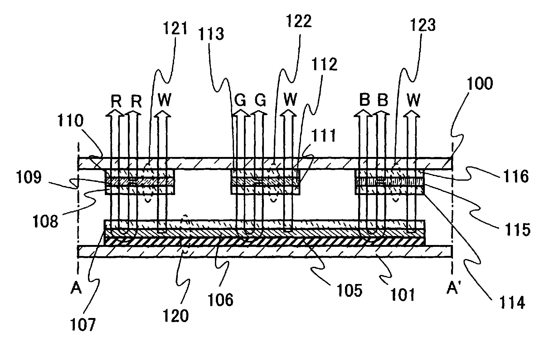
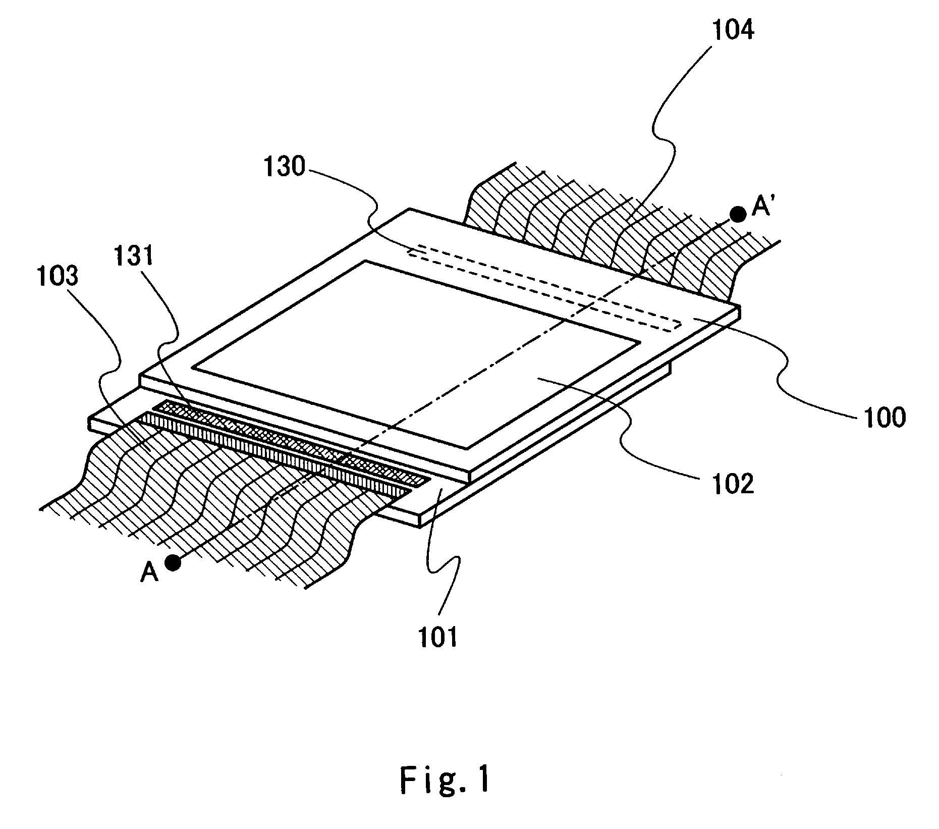
[0123]In this embodiment mode, a display device formed by attaching a substrate having a white (W) organic light emitting element to a substrate having red (R), green (G), and blue (B) organic light emitting elements, will be described. A perspective view of a display device according to the present invention is shown in FIG. 1. In FIG. 1, reference numeral 100 is a first substrate over which red (R), green (G), and blue (B) organic light emitting elements are formed; 101, a second substrate over which a white organic light emitting element is formed; and 102, a display screen. Reference numerals 103 and 104 are FPCs (flexible printed circuits); and 130 and 131, peripheral driver circuits. Over the first substrate 100, a pixel portion (not shown) including a plurality of organic light emitting elements and the peripheral driver circuit 130 are formed. Over the second substrate 101, a pixel portion (not shown) including a plurality of organic light emitting elements and the periphera...

embodiment mode 2

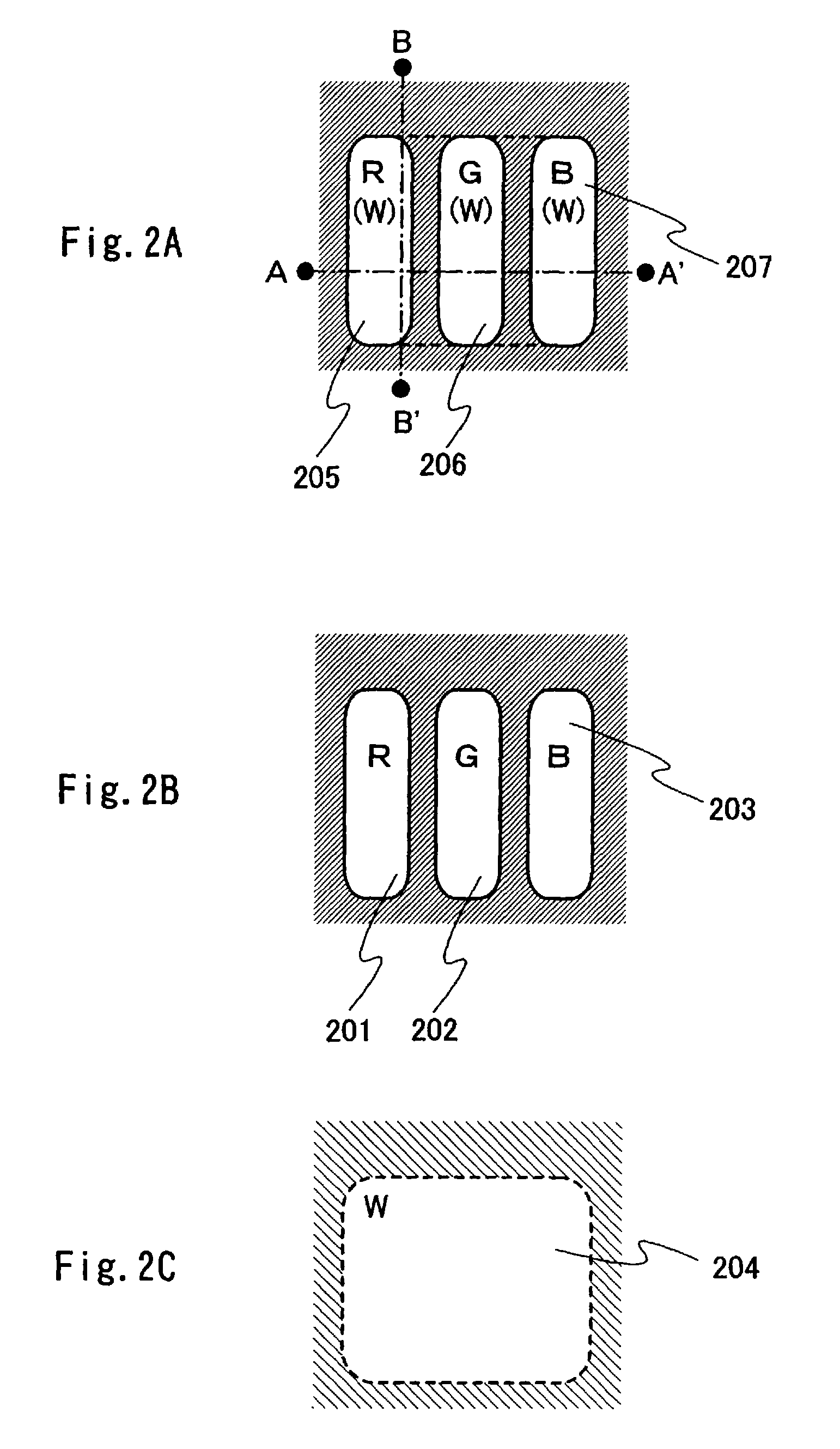
[0161]In this embodiment mode, an example according to the case B of the first structure of the present invention will be described. Specifically, a case in which a dot of a white organic light emitting element is provided over a second substrate so as to face a dot of a red organic light emitting element provided over a first substrate, a dot of a white organic light emitting element is provided over the second substrate so as to face a dot of a green organic light emitting element provided over the first substrate, and a dot of a white organic light emitting element is provided over the second substrate so as to face a dot of a blue organic light emitting element provided over the first substrate, will be described. Note that, a case of forming a display screen over the first substrate (that is, an image is displayed on the first substrate side) will be described in this embodiment mode.

[0162]FIGS. 18A to 18C show pixel structures of a display device according to this embodiment m...


PUM


Abstract

To improve an image quality of an organic EL display by utilizing characteristics of a dual emission type organic light emitting element. A display device includes a first substrate over which a plurality of organic light emitting elements are provided and a second substrate over which an organic light emitting element is provided. The first and second substrates are facing each other. At least either the organic light emitting elements provided over the first substrate or the organic light emitting element provided over the second substrate emit / emits light toward both surfaces of the first or second substrate. Light emitting regions of the organic light emitting elements provided over the first substrate are overlapped with a light emitting region of the organic light emitting element provided over the second substrate as seen from the second substrate.

Description

BACKGROUND OF THE INVENTION[0001]1. Field of the Invention[0002]The present invention relates to a display device including an organic light emitting element. In particular, the present invention relates to a display device (an organic EL display) including a light emitting element having an organic compound (an organic light emitting element) which emits light by being applied with electronic field. Moreover, the present invention relates to an electronic appliance using such a display device for a display portion.[0003]2. Description of the Related Art[0004]An organic light emitting element has a structure in which a layer containing an organic compound (an organic light emitting material) which generates electroluminescence by being applied with electric field (hereinafter, referred to as an organic compound layer), is interposed between a pair of electrodes (a first electrode and a second electrode). The organic light emitting material is classified into a material which can con...

Claims


Application Information

Patent Timeline
Patent Type & Authority Patents(United States)
IPC IPC(8): H01J63/04
CPCH01L25/048H01L27/3213H01L27/3267H01L2924/0002H01L2924/00H10K59/90H10K59/351H10K59/128H05B33/12
Inventor HIRAKATA, YOSHIHARUIBE, TAKAHIRO
Owner SEMICON ENERGY LAB CO LTD
Why Eureka
Try Eureka