Supercharge Your Innovation With Domain-Expert AI Agents!

Transformer structure

Inactive Publication Date: 2010-05-11
SPI ELECTRONICS
View PDF8 Cites 9 Cited by
  • Summary
  • Abstract
  • Description
  • Claims
  • Application Information

AI Technical Summary

Benefits of technology

[0004]Since the conventional transformer is limited by the safety regulation and the power output property, one way to improve the power insulation strength is to alter the bobbin design of the transformer for providing better adaptability to all kinds of circuits and simultaneously conforming to the safety regulation.
[0005]The present invention provides a transformer structure including an iron core set, a main bobbin, and two sub-bobbins. The main bobbin includes a primary winding area for winding a first coil, a main bobbin through hole longitudinally mounted in and penetrating through the main bobbin, and two assembling troughs respectively formed at two ends of the main bobbin through hole. The two sub-bobbins are respectively accommodated in the two assembling troughs and respectively include a secondary winding area for winding a second coil and a sub-bobbin through hole communicated with the main bobbin through hole for penetrating the iron core set. Therefore, the sub-bobbins are mounted in two extended assembling troughs of the main bobbin, the first coil is wound on the primary winding area at the outer side of the main bobbin, and the first coil is separated from the second coil not only by horizontal distance but also by the assembling troughs of the main bobbin, so as to provide enhanced insulation strength. Moreover, since the two sub-bobbins can be respectively wound by two independent second coils, the input and the output of the transformer of the present invention can be implemented as the one-to-two type transformer, so as to improve adaptability. Furthermore, since the main bobbin and the sub-bobbins provide sufficient insulation strength, the whole dimension of the transformer can be reduced under the safety regulation, and simultaneously, the output and input isolation also can be guaranteed for preventing the output power from being influenced, thereby increasing the adaptability to different circuits, especially the circuit used in driving discharging lamp, such as, back light module. Therefore, the transformer structure of the present invention provides enhanced insulation strength for conforming the safety regulations.

Problems solved by technology

However, as the transformer works, a large amount of current will be generated and the voltage will have an apparent variation, so that the transformer should conform to severe safety regulation before using.
And, for conforming to the safety regulation, on one hand, the transformer is always enlarged for providing sufficient insulation distance for the coils, and thus, obviously, under the same electric characteristic, the miniaturization of the transformer is restricted by the safety regulation.
However, the use of two transformers increases the cost and also the volume.
Consequently, the size and the adaptability of the transformer are restricted by the insulation strength and the power waveform at the primary and the secondary sides.

Method used


Image

  • Transformer structure
  • Transformer structure
  • Transformer structure

Examples


Embodiment Construction

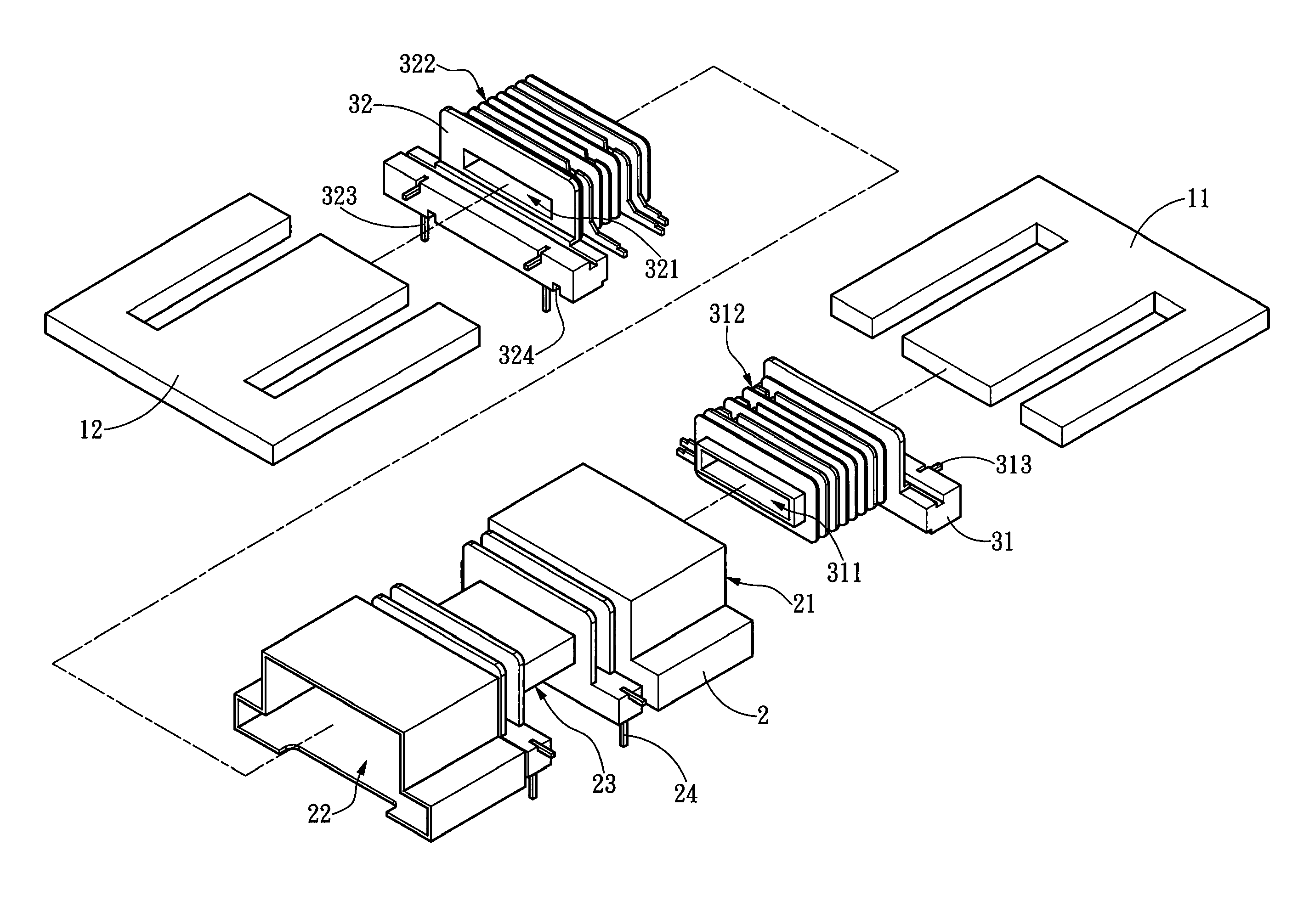
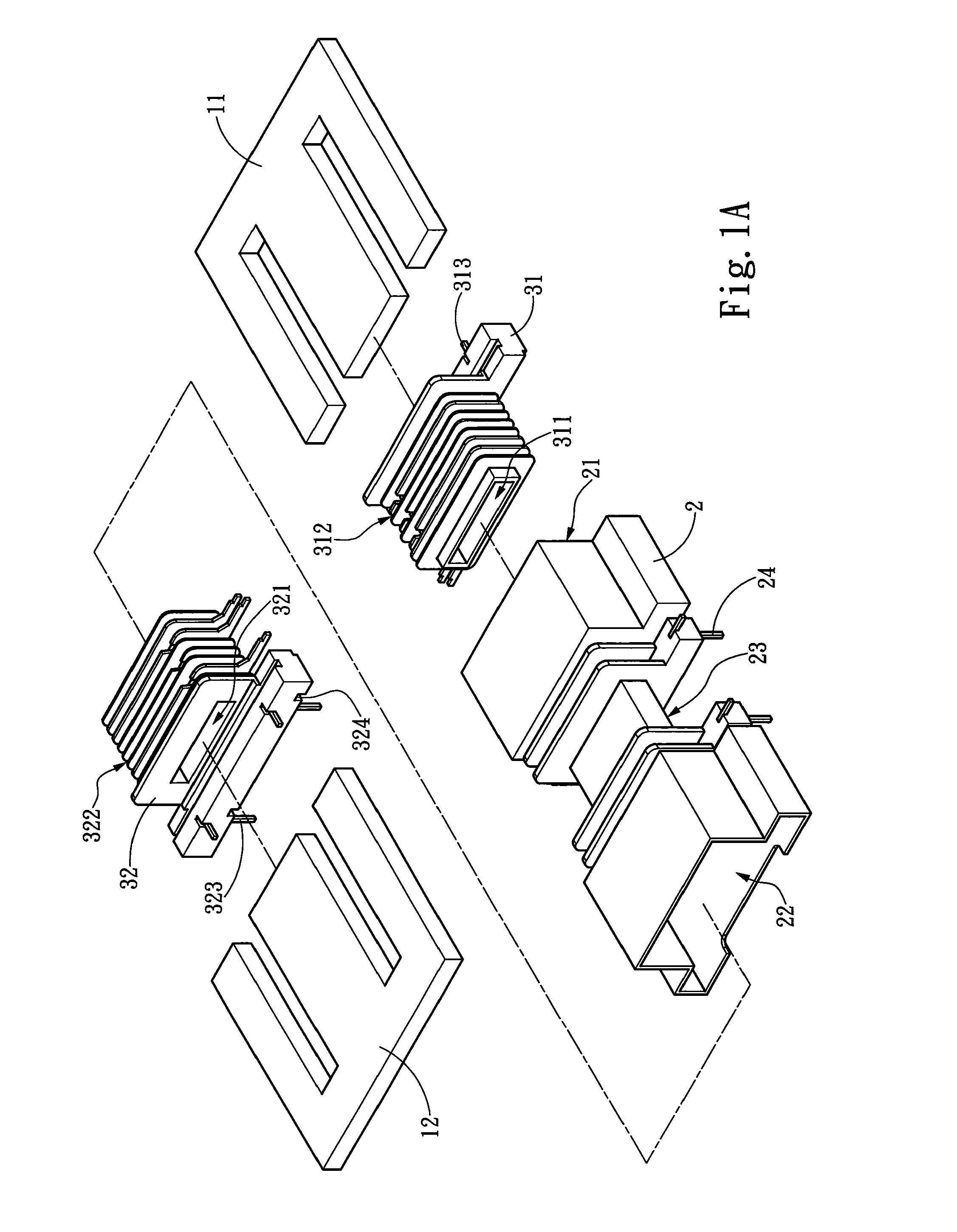
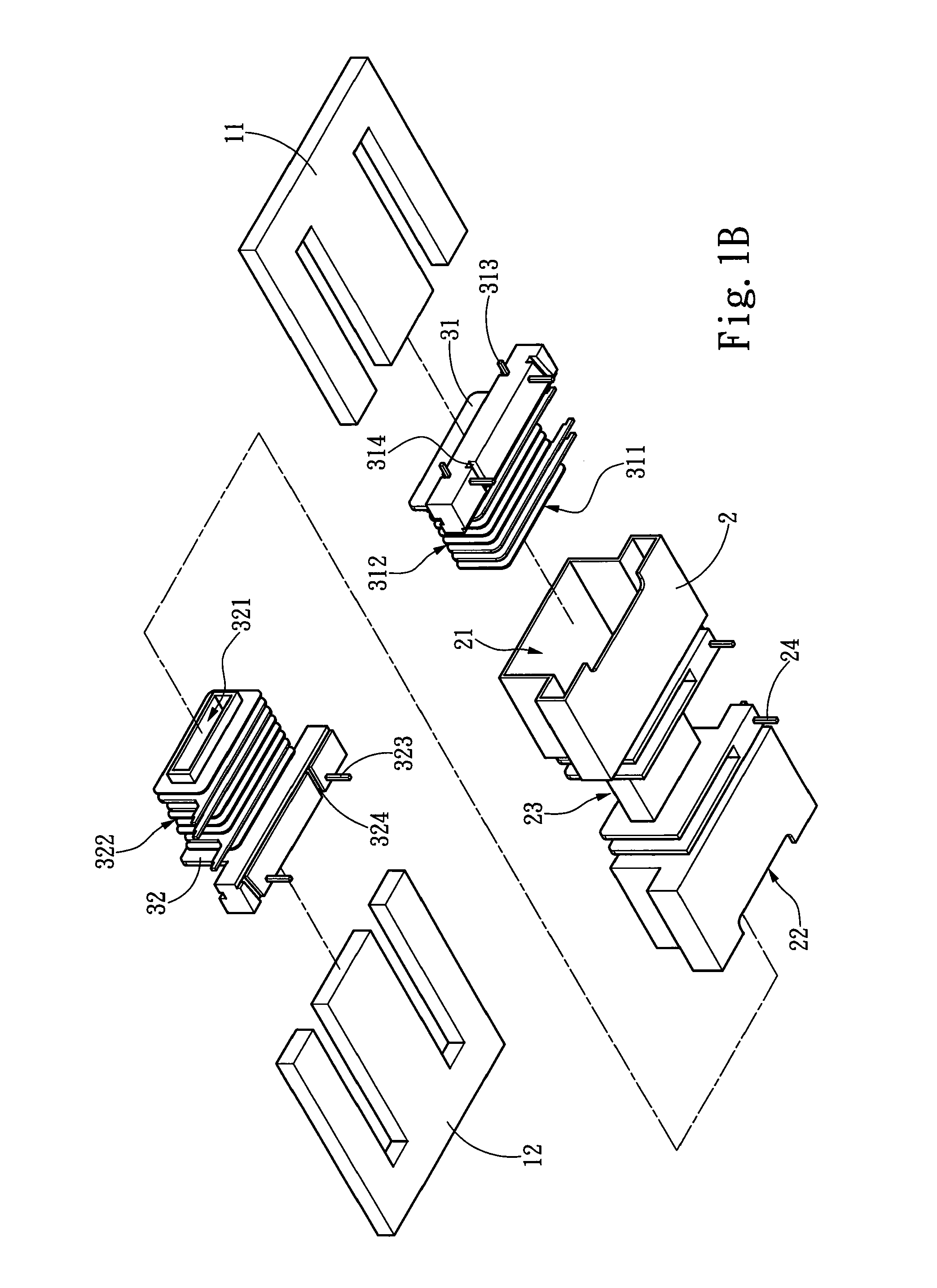
[0014]The present invention provides a transformer structure including an iron core set, a main bobbin 2 and two sub-bobbins 31, 32 respectively mounted at two ends of the main bobbin 2. As shown in FIG. 1A and FIG. 1B, the main bobbin 2 includes a primary winding area 23 for winding a first coil 4 (as shown in FIG. 5), a main bobbin through hole 25 (as shown in FIG. 4) longitudinally penetrating through the main bobbin 2, and two assembling troughs 21, 22, which are respectively mounted at and communicated with two end openings of the main bobbin through hole 25 and have a section larger than that of the main bobbin through hole 25 for respectively accommodating two sub-bobbins 31, 32. The two sub-bobbins 31, 32 respectively have sub-bobbin through holes 311, 321 which communicate with the main bobbin through hole 25 to form a run-through space, so that the iron core set can penetrate through the main bobbin through hole 25 and the sub-bobbin through holes 311, 321. Here, the iron ...


PUM


Abstract

A transformer structure includes an iron core set, a main bobbin, and two sub-bobbins. The main bobbin includes a primary winding area for winding a first coil, a main bobbin through hole longitudinally mounted in and penetrating through the main bobbin, and two assembling troughs respectively formed at two ends of the main bobbin through hole. The two sub-bobbins are respectively accommodated in the two assembling troughs and respectively include a secondary winding area for winding a second coil and a sub-bobbin through hole communicated with the main bobbin through hole for penetrating the iron core set. Therefore, the sub-bobbins are mounted in two extended assembling troughs of the main bobbin, the first coil is wound on the primary winding area at the outer side of the main bobbin, and the first coil is separated from the second coils not only by horizontal distance but also by the assembling troughs.

Description

FIELD OF THE INVENTION[0001]The present invention is related to a transformer structure, and more particularly to a bobbin structure of the transformer which can be wound by at least two sets of coils at the primary side and the secondary side.BACKGROUND OF THE INVENTION[0002]Various types of transformers are developed for adapting different functional demands, so that when designing transformer, it should consider many properties, such as, transformer ratio, current and loss, and dimension, for example, as the output power and the properties of the transformer are qualified, naturally, the smaller the size, the more different kinds of electric equipment the transformer can be adapted thereto. However, as the transformer works, a large amount of current will be generated and the voltage will have an apparent variation, so that the transformer should conform to severe safety regulation before using. And, for conforming to the safety regulation, on one hand, the transformer is always ...

Claims


Application Information

Patent Timeline
IPC IPC(8): H01F27/30
CPCH01F27/29H01F38/10H01F27/326H01F27/30
Inventor HSIEH, WEN SEN
Owner SPI ELECTRONICS
Features
  • R&D
  • Intellectual Property
  • Life Sciences
  • Materials
  • Tech Scout
  • Unparalleled Data Quality
  • Higher Quality Content
  • 60% Fewer Hallucinations
Learn More