Display device and driving method thereof

a technology of a display device and a driving method, which is applied in the direction of instruments, computing, antibacterial agents, etc., can solve the problems of difficult timing adjustment, affecting the transmission frequency, and imbalanced phase relation between the transmission clock and the start pulse sp, so as to achieve the effect of easy timing adjustmen

Inactive Publication Date: 2010-05-11
SHARP KK
View PDF25 Cites 4 Cited by
  • Summary
  • Abstract
  • Description
  • Claims
  • Application Information

AI Technical Summary

Benefits of technology

[0034]Under two-split drive structure, an object of the present invention is to provide a display device which easily adjusts timings for sending signals to source drivers SD and a driving method thereof.
[0038]Further, the controlling circuit supplies data signals to a driving circuit in at least one of the display regions by rearranging an order of data signals to be in line with an order of data signals supplied to the other one of the display regions. As an example, assume that the first and the second display regions are provided adjacently. When carrying out regular display with no left-and-right inversion, the controlling circuit supplies data signals to driving circuits in the left-side first display region by rearranging data in a reversed order. This makes it possible to carry out normal regular display even when the two driving circuits start acquiring data signals.
[0039]Start signals can be sent to the two driving circuits through a shortest transmission distance, because the start signals are sent to the two driving circuits closest to the border between the first and the second display regions, the two driving circuits adjacently provided in a center region. This enables suppressing the amount of retardation of start pulses and equalizing the amount of retardation of start signals sent to the two driving circuits. Thus, it is possible to facilitate adjusting a phase between other controlling signals and start signals, which are sent to the driving circuits. That is, timings for sending signals to driving circuits can be easily adjusted under the two-split drive structure.

Problems solved by technology

On the other hand, in a state shown in FIG. 19, the phase relation between a transmission clock and a start pulse SP becomes imbalanced.
As a result, it becomes hard to adjust timings, thereby restricting a transmission frequency.
This problem is prominent in larger liquid crystal display devices having a long distance for transmitting signals, or in liquid crystal display devices carrying out high-definition display at a high transmission frequency.
However, this publication describes neither start pulses SP nor the problem due to retardation of start pulses, which serves no solution for the problem.

Method used


Image

  • Display device and driving method thereof
  • Display device and driving method thereof
  • Display device and driving method thereof

Examples


first embodiment

[0060]With reference to figures, the following describes one embodiment of the present invention. According to the arrangement of the present invention, an active matrix type liquid crystal display device (hereafter referred to as liquid crystal display device) is used as an example of a display device of the present invention. The structure of the liquid crystal display device is shown in FIG. 11.

[0061]With reference to FIGS. 2 through 5, a principle of the liquid crystal display device of the present embodiment is described.

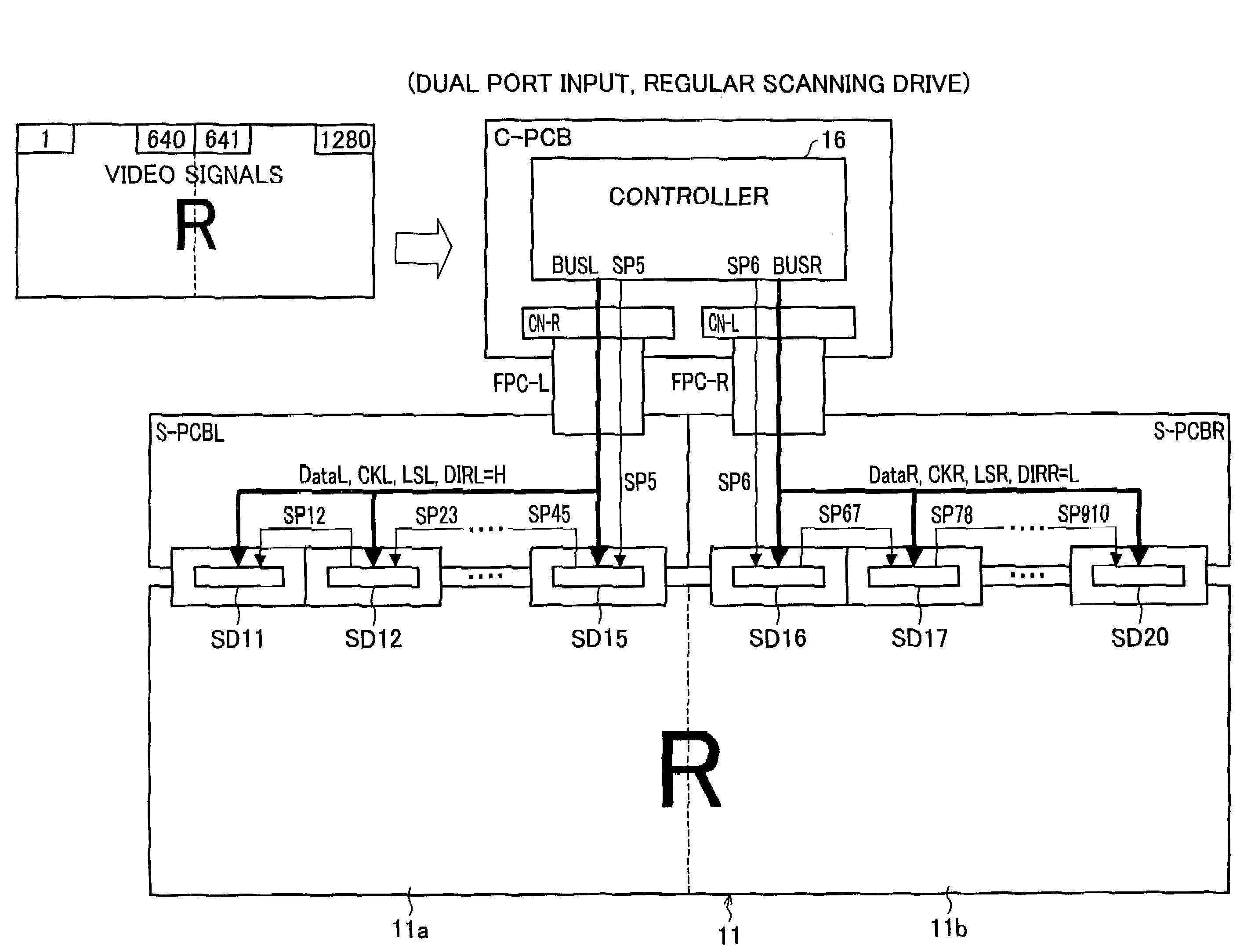
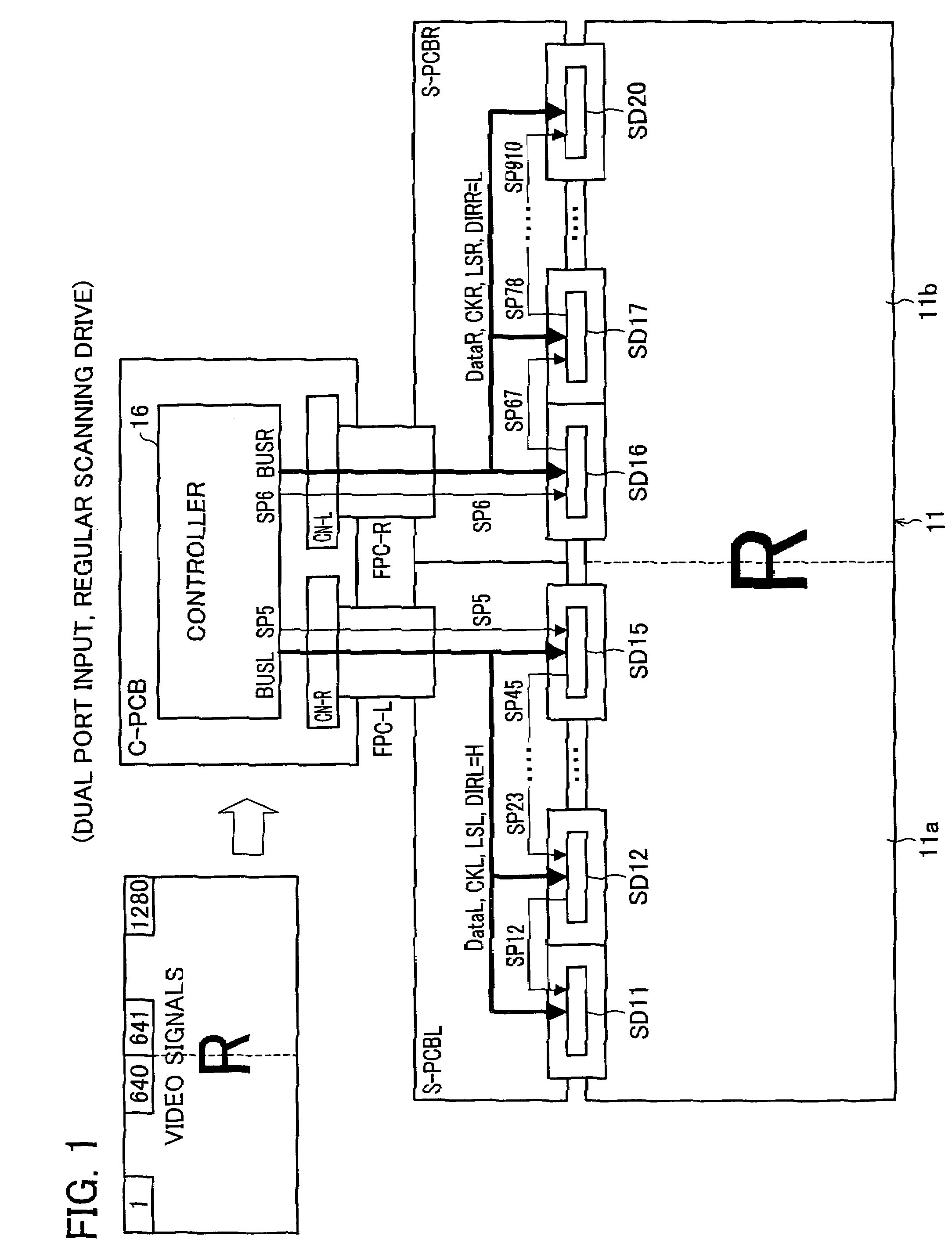
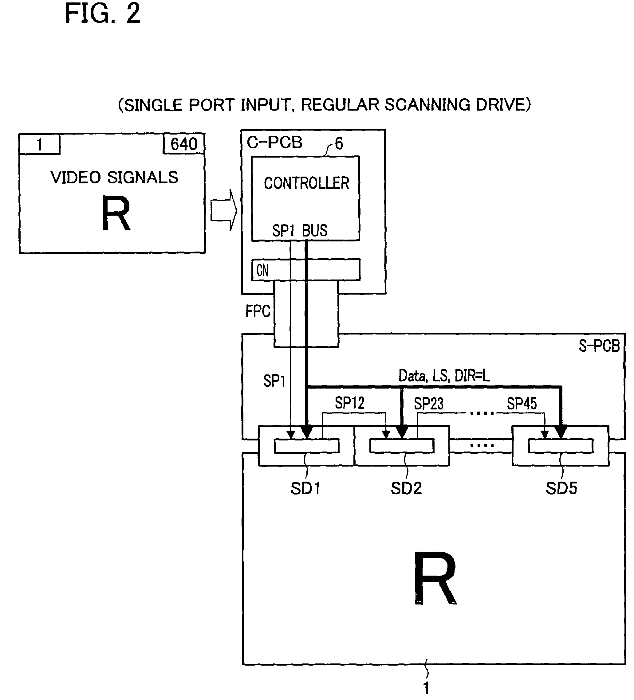
[0062]FIG. 2 illustrates a liquid crystal display device with no two-split drive. This liquid crystal display device includes a liquid crystal display panel 1 having a horizontal resolution of 640 dots, for example. That is, there are 640 pixels on one horizontal line. Note that, a gate driver is omitted for simplification in FIG. 2.

[0063]As shown in FIG. 2, the liquid crystal display device has a plurality of source drivers SD, to which source bus lines are ev...


PUM


Abstract

A display device includes a left and a right panel sections provided adjacently along a sequence of a plurality of data signal lines, and a plurality of source drivers which are provided along a sequence of the data signal lines and correspond to the panel sections. A controller sends data signals to the respective source drivers in parallel, and a start signal to one of the source drivers in each of the display panel. In each panel section, an operation of acquiring data signals sequentially shifts from the source driver having received the start signal to the next source driver. The controller sends the start signals to the two source drivers closest to a border between the two display regions, and rearranges an order of data signals, which are supplied to source drivers in one of the display regions, to be in line with an order of data signals which are supplied to the other one of the display regions.

Description

[0001]This Nonprovisional application claims priority under 35 U.S.C. §119(a) on Patent Application No. 2004 / 224814 filed in Japan on Jul. 30, 2004, the entire contents of which are hereby incorporated by reference.FIELD OF THE INVENTION[0002]The present invention relates to a display device such as flat panel display devices typified by liquid crystal display devices, and its driving method.BACKGROUND OF THE INVENTION[0003]Currently, flat panel displays such as liquid crystal display devices or the like have been used for display devices of television sets, personal computers, or the like. The following describes conventional arts of a liquid crystal display device representing flat panel displays as an example. Note that, in the following description, data1, data2, data3 . . . are display data to be respectively written in pixel1, pixel2, pixel3 . . . on a single horizontal line of the liquid crystal display panel in regular display mode, assuming that the pixel1, pixel2, pixel3 ....

Claims


Application Information

Patent Timeline
Patent Type & Authority Patents(United States)
IPC IPC(8): G09G5/00
CPCG09G3/3648G09G2340/0492G09G3/3685A61P31/04G09G3/20G09G3/36
Inventor SHIRAISHI, TAI
Owner SHARP KK
Why Eureka
Try Eureka