
Liquid crystal panel and projection liquid crystal display apparatus having particular light-shielding film

a liquid crystal display and liquid crystal panel technology, applied in the direction of projectors, optics, instruments, etc., can solve the problems of affecting the reliability of the display device, affecting the display effect, and affecting the appearance of the light, so as to prevent moisture from entering the display device, improve the specific resistance, and improve the effect of adhesion

Active Publication Date: 2010-05-11
JAPAN DISPLAY WEST
View PDF12 Cites 4 Cited by
  • Summary
  • Abstract
  • Description
  • Claims
  • Application Information

AI Technical Summary

Benefits of technology

"The invention provides a liquid crystal panel with a resin light-shielding film that reduces problems such as electrification and light leakage. The light-shielding film has a frame portion and a middle portion with higher specific resistance and light-shielding properties. The frame portion prevents separation from the substrate and moisture entering the panel, while the middle portion prevents electrification and light leakage. The frame portion is positioned at least one pixel away from the outermost pixels to prevent display quality issues. The frame portion has higher thermal conductivity to prevent temperature increase and produce high quality images. The invention also provides a projection liquid crystal display apparatus with the improved light-shielding film to reduce light leakage more effectively in a projection type than in a direct-view type."

Problems solved by technology

Therefore, the resin light-shielding film is liable to cause light leakage in comparison with the chromium light-shielding film.
Light leakage tends to be conspicuous when a high-intensity backlight is used.
If the light-shielding film separates, moisture enters the liquid crystal panel through an edge of the panel to degrade the reliability.
If the resin light-shielding film is formed using a resist film, the above problems are liable to occur because of the low OD value and adhesion.

Method used


Image

  • Liquid crystal panel and projection liquid crystal display apparatus having particular light-shielding film
  • Liquid crystal panel and projection liquid crystal display apparatus having particular light-shielding film
  • Liquid crystal panel and projection liquid crystal display apparatus having particular light-shielding film

Examples


Embodiment Construction

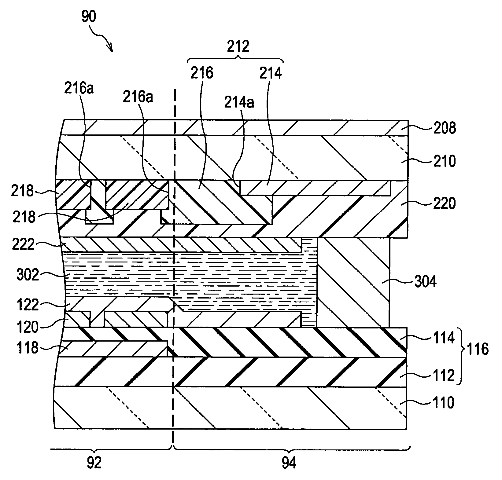
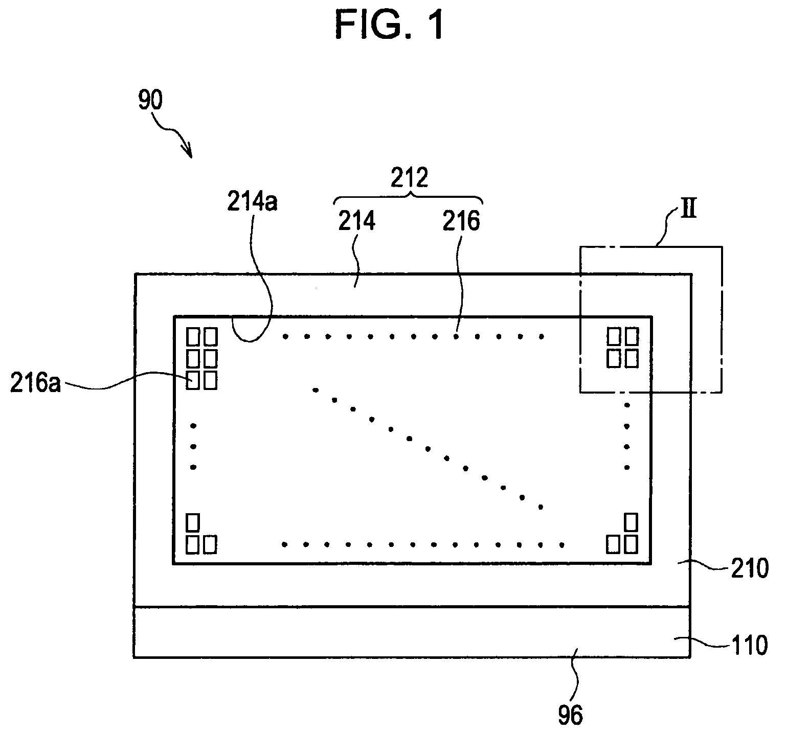
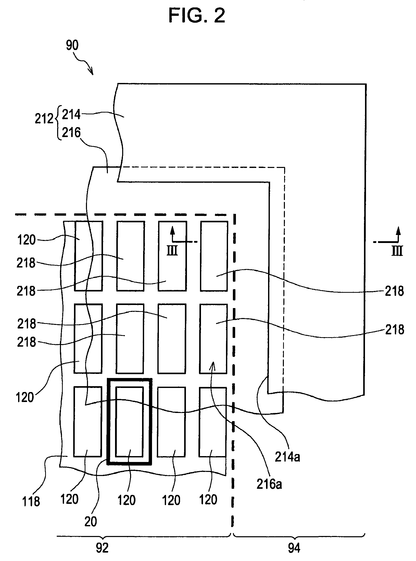
[0031]FIG. 1 shows a plan view of a liquid crystal panel 90 according to an embodiment of the invention, and FIG. 2 shows an enlarged view of the portion surrounded by dotted chain line II in FIG. 1. FIG. 3 is a sectional view of the portion shown in FIG. 2 taken along line III-III. Some of the parts shown in FIG. 3 are omitted in FIGS. 1 and 2.

[0032]The liquid crystal panel 90 has a pixel region 92 where a plurality of pixels 20 are arranged. For the sake of easy understanding, one of the pixels 20 is designated by a bold line in FIG. 2. While FIG. 2 shows pixels 20 arranged in a matrix manner, the pixels 20 may be arranged in a delta form. At least the outermost pixels 20 may be used as dummies that do not directly contribute to displaying images.

[0033]The region of the liquid crystal panel 90 outside the pixel region 92 is referred to as the surrounding region 94.

[0034]The liquid crystal panel 90 includes a first optically transparent substrate 110 and a second optically transpar...


PUM

PropertyMeasurementUnit
ODaaaaaaaaaa
ODaaaaaaaaaa
thicknessaaaaaaaaaa

Abstract

A liquid crystal panel includes a first substrate having pixels defining a pixel region, and pixel electrodes and a common electrode disposed in the pixel region on the first substrate. The pixel electrodes are disposed for the respective pixels. The liquid crystal panel also includes a second substrate opposing the first substrate and a light-shielding film disposed on the second substrate. The light-shielding film includes a frame portion surrounding the pixel region and a middle portion disposed at least in the pixel region. The middle portion is made of a material having a higher specific resistance than the frame portion. The frame portion is made of a material having a higher light-shielding property than the middle portion.

Description

BACKGROUND[0001]1. Technical Field[0002]The present invention relates to liquid crystal panels and projection liquid crystal display apparatuses, and particularly to a liquid crystal panel including a resin light-shielding film and a projection liquid crystal display apparatus using the liquid crystal pane.[0003]2. Related Art[0004]A twisted nematic (TN) or electrically controlled birefringence (ECB) liquid crystal panel has pixel electrodes and a common electrode that are disposed on their respective substrates. On the other hand, a fringe field switching (FFS) or in-plane switching (IPS) liquid crystal panel has pixel electrodes and a common electrode that are disposed on the same substrate.[0005]In the TN type, a chromium (Cr) light-shielding film is generally formed as a black matrix on the substrate having the common electrode. Since chromium has a high light reflectance, the light-shielding film may be made of a composite including a chromium layer and a low-reflectance chromi...

Claims


Application Information

Patent Timeline
Patent Type & Authority Patents(United States)
IPC IPC(8): G02F1/1333G02F1/1335G02F1/1343
CPCG03B21/00G02F1/133512G03B21/006G02F1/1335
Inventor MAEDA, KAZUYUKI
Owner JAPAN DISPLAY WEST
Learn More