Optical birefringence coronagraph

a birefringence coronagraph and optical technology, applied in the field of optical technology, can solve the problem of frequently complicated detection of planets outside the solar system

Active Publication Date: 2010-05-11
NORTHROP GRUMMAN SYST CORP
View PDF17 Cites 11 Cited by
  • Summary
  • Abstract
  • Description
  • Claims
  • Application Information

AI Technical Summary

Problems solved by technology

Detecting planets outside of the solar system is frequently complicated by the relative proximity of extrasolar planets to the stars they orbit.

Method used


Image

  • Optical birefringence coronagraph
  • Optical birefringence coronagraph
  • Optical birefringence coronagraph

Examples


Embodiment Construction

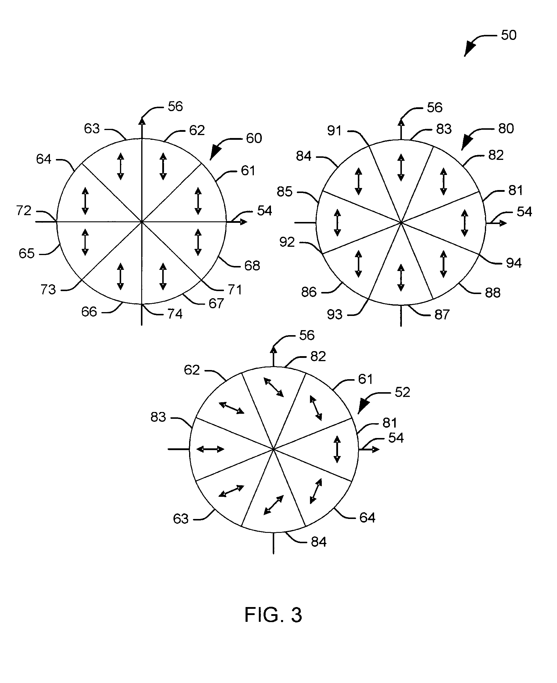
[0011]In accordance with an aspect of the present invention, a coronagraph that utilizes a radial or azimuthal polarization of incident light to attenuate light from an undesired source is provided. In order to convert a linearly polarized beam into a radially / azimuthally polarized beam effectively, this invention employs an orientation-independent polarization rotator using a half-wave plate having a characteristic c-axis, that is an axis in a birefringent material along which the electric field portion of electromagnetic field radiation experiences extraordinary index of refraction. When passing through a half-wave plate, a linearly polarized beam will have its polarization changed to the other side of the c-axis. Mathematically, it can be written as a′=2b−a, where b is the angle of the c-axis, a and a′ are the polarization angles of the input and output beams. The concept can be used to convert a linearly polarized beam into a “nearly” radially or azimuthally polarized beam.

[0012...


PUM


Abstract

Systems and methods for attenuating light from undesired sources in a coronagraph apparatus are provided. The coronagraph includes a first imaging lens that receives light representing a desired image and an undesired central image and a reimaging system that mitigates the undesired central image. The reimaging system includes a composite half-wave plate assembly that includes a plurality of angular half-wave plate sections. Each of the plurality of angular half-wave plate sections have two congruent sides that meet at an apex substantially at a center of the composite half-wave plate. A characteristic c-axis associated with a given angular half-wave plate section is aligned differently from the respective characteristic c-axes of at least two angular half-wave plate sections in substantial contact with the two sides of the given angular half-wave plate section. A fixation element engages the half-wave plate sections to maintain the angular half-wave plate sections in a desired arrangement.

Description

CROSS REFERENCE TO RELATED APPLICATIONS[0001]This application is related to the following commonly assigned co-pending U.S. patent application Ser. No. 11 / 637,289, filed on Dec. 12, 2006, entitled: “Conversion of the Polarization of Light Via a Composite Half-Wave Plate,”; which is being filed contemporaneously herewith and is incorporated herein by reference.TECHNICAL FIELD[0002]The present invention relates generally to optical technology, and more particularly to an optical birefringence coronagraph.BACKGROUND OF THE INVENTION[0003]Detecting planets outside of the solar system is frequently complicated by the relative proximity of extrasolar planets to the stars they orbit. Since planets can be located only by the reflected light of their star, the star will be significantly brighter than the planet of interest, in some cases on the order of ten million times brighter. In light of the relative proximity of a planet to its star, it is necessary to attenuate the light of the star t...

Claims


Application Information

Patent Timeline
Patent Type & Authority Patents(United States)
IPC IPC(8): G02B5/30G02B27/28
CPCG01J1/04G01J1/0414G02B27/28G02B5/3083G02B23/00G01J1/0418Y10S359/90
Inventor SHIH, CHUN-CHING
Owner NORTHROP GRUMMAN SYST CORP
Why Eureka
Try Eureka