
Optical vortex coronagraph scatterometer

a scatterometer and optical vortex technology, applied in the field of optical vortex coronagraph scatterometer and method, can solve the problems of loss of signal in the glare of the illumination source, inability of typical devices to accurately determine scattering spectra at very low angles, and difficulty in distinguishing low-angle scattered light from more intense unscattered laser ligh

Active Publication Date: 2019-08-27
ROCHESTER INSTITUTE OF TECHNOLOGY
View PDF16 Cites 1 Cited by
  • Summary
  • Abstract
  • Description
  • Claims
  • Application Information

AI Technical Summary

Benefits of technology

The present patent text describes an optical vortex coronagraph scatterometer and a method for measuring the angular spectrum of scattered light. The scatterometer includes a light source, a scattering cell, a circular aperture, a pivot point, and a first and second lens. The method involves transmitting light through the scattering cell at different angles and measuring the low-angle scattered light. Overall, this optical tool can provide accurate and reliable measurements of scattered light, which can be useful in various fields such as optical communications or biological imaging.

Problems solved by technology

Typical devices are unable to accurately determine scattering spectra at very low angles where the unscattered light is much brighter than the scattered light.
However, in the weak scattering regime typical of this method, it is difficult to distinguish low-angle scattered light from the more intense unscattered laser light, especially near the zero angle.
That is, the signal is lost in the glare of the illumination source.
This resulted in inaccurate low-angle scattering values or estimates which are used to approximate the needed data.

Method used


Image

  • Optical vortex coronagraph scatterometer
  • Optical vortex coronagraph scatterometer
  • Optical vortex coronagraph scatterometer

Examples


example 1

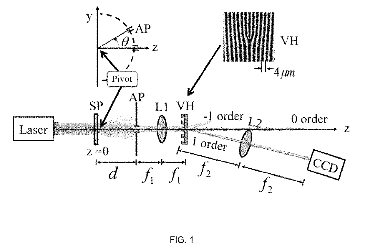
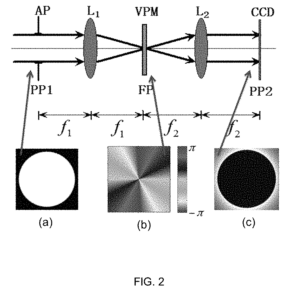
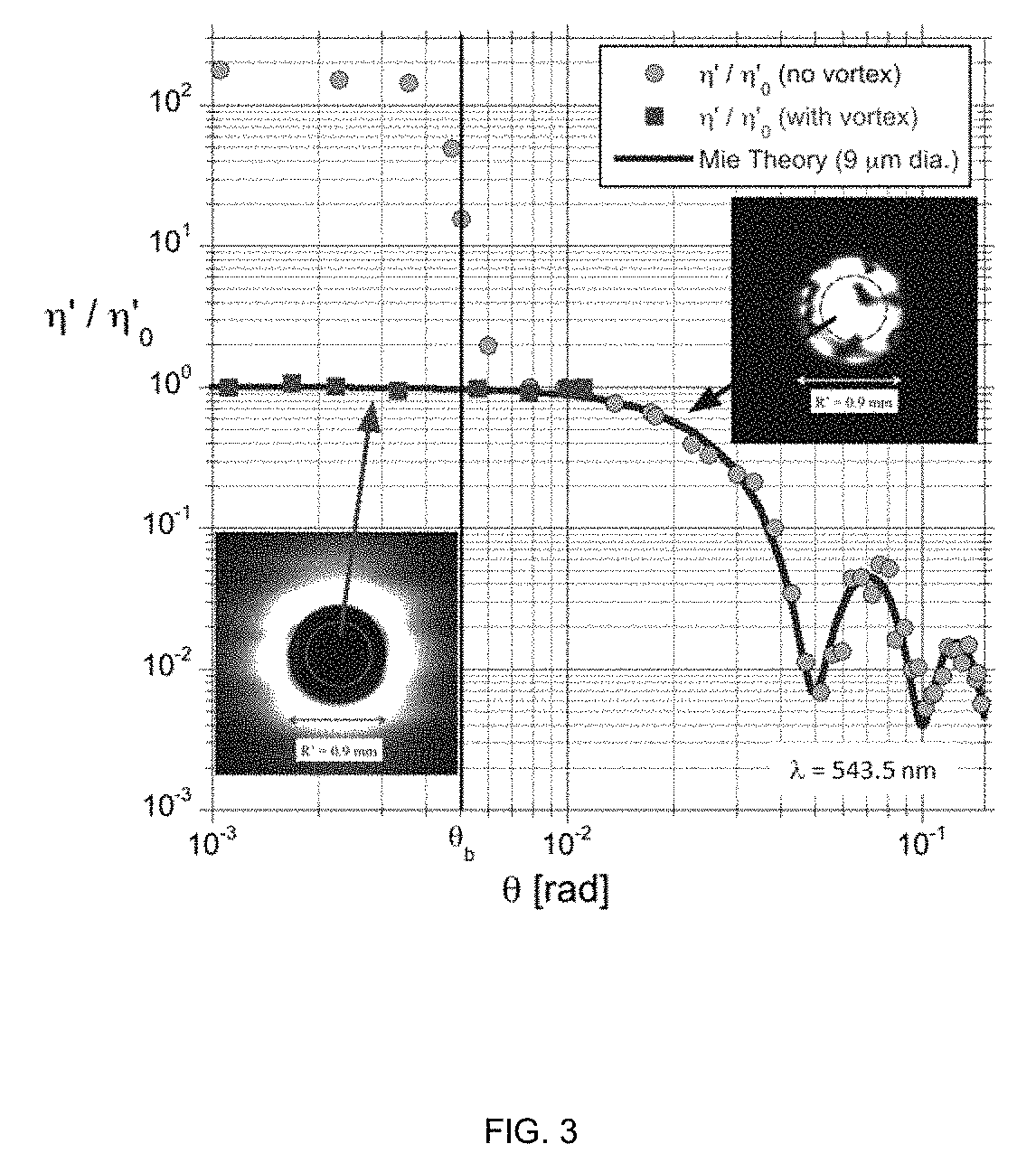
[0026]This Example describes experimental results whereby a vortex coronagraph is used to measure the angular spectrum of scattered light, including at the zero angle. To measure the angular spectrum of scattered light an optical vortex coronagraph, as illustrated in FIG. 1 was used. A green HeNe laser (λ=543.5 nm) having a collimated beam radius (w=0.88 mm) was made normally incident to a thin scattering cell of inner path length Lc=0.50 mm. The cell contained a dilute water suspension of polystyrene spheres (certified mean diameter Ds=8.93 μm±0.07 μm, refractive index n≅1.597) at an approximate concentration of C=5×103 mm−3=0.16C0 where C0=4 / πDs2L=3.1×104 mm−3 is the scattering extinction parameter. A portion of the scattered light is transmitted through an aperture (AP) with diameter DAP=0.30 mm at a distance d=213 mm from the sample. According to the van Cittert-Zernike theorem, the coherence diameter of the extended scattering source, as measured at AP was Dcoh≈λd / w=0.13 mm. Th...


PUM

PropertyMeasurementUnit
beam divergence angleaaaaaaaaaa
focal lengths f1aaaaaaaaaa

Abstract

An optical vortex coronagraph scatterometer including a light source of wavelength λ, a scattering cell in optical communication with the light source, a circular aperture having a radius R at a distance d from the scattering cell in optical communication with the light source, a pivot point between the circular aperture and the scattering cell allowing relative movement of the light source and the scattering cell with respect to the circular aperture, a first lens at a focal length f1 between the circular aperture and an optical vortex element, and a second lens at a focal length f2 between the optical vortex element and a detector; and method for determining a scattering spectra at low and zero angles is disclosed.

Description

CROSS REFERENCE[0001]This application claims the benefit of the filing date of U.S. Provisional Patent Application Ser. No. 62 / 384,457, filed Sep. 7, 2016, which is hereby incorporated by reference in its entirety.[0002]This invention was made with government support under grant number Grant No. ECCS-1309517 awarded by the National Science Foundation. The government has certain rights in this invention.FIELD[0003]The present disclosure relates to an optical vortex coronagraph scatterometer and method, and in particular to an optical vortex coronagraph scatterometer and method capable of accurately measuring the complete scattering spectrum at the zero, low and high angles.BACKGROUND[0004]Scatterometers are used in many industrial applications from pharmaceuticals, paint, food production, and surface inspection owing to the ability to quickly and reliably characterize the size and distribution of microscopic particles. Scatterometers obviate the need for direct imaging to characteriz...

Claims


Application Information

Patent Timeline
Patent Type & Authority Patents(United States)
IPC IPC(8): G01N15/14
CPCG01N15/0211G01N15/1434
Inventor SWARTZLANDER, JR., GROVER A.
Owner ROCHESTER INSTITUTE OF TECHNOLOGY
Learn More