Human-machine interface for a control system

a technology of human-machine interface and control system, which is applied in the direction of program control, electric controller, instruments, etc., can solve the problems of incongruity between different equipment interfaces, time-consuming and laborious process of obtaining information about alarms or devices, and considerable time may be required to search by name or system identification, etc., to achieve efficient multi-modal communication and reduce stress

Active Publication Date: 2010-05-11
ABB (SCHWEIZ) AG
View PDF9 Cites 50 Cited by
  • Summary
  • Abstract
  • Description
  • Claims
  • Application Information

AI Technical Summary

Benefits of technology

[0012]The general aim of this invention is to provide a fast and efficient way to locate specific process or equipment control data held by a control system. The user points to the valve or mixer or press on the model and is routed to the control system information held for that part or device. Online real time data, setpoints, configuration data, service history, any information associated with that device by the control system may be intuitively found and then retrieved. The information obtained may be displayed to a field operator (e.g. an operator, a service technician, a maintenance person, OEM, a process engineer, etc. or to a remote person, expert, other operator etc. First of all, the HMI and the described methods provide relevant information intuitively and quickly to the field operator for monitoring and interaction with the industrial process or device.
[0017]The presence of field operators and other personnel on the plant floor is often perceived as a stress factor for control room operators. This is because the control room operators do not know the exact position and status of these people and direct communication is not always possible. A 3D model of the plant with avatars representing the exact position of all personnel can reduce this stress. Furthermore, advanced information and communication technology can establish efficient multi-modal communication channels quickly. The 3D model of the plant can also aid operators in assisting personnel on the plant floor or when communicating with external or remote experts. The 3D model can give detailed information about the immediate surroundings of the field operator that needs assistance, for example by highlighting the electric system, pipelines, valves, pumps or other relevant components.Production Managers Ensuring High Process PerformanceTask: Identify bottlenecks and inefficiencies in current production systemIndustry: Oil & Gas

Problems solved by technology

The different equipment interfaces may also often be inconsistent with respect to each other.
In addition, the process of obtaining information about an alarm or about a device may take considerable time, and may require that an operator browses through many databases.
A considerable amount of time may be necessary to search by name or system identification for information about a device or process.

Method used


Image

  • Human-machine interface for a control system
  • Human-machine interface for a control system
  • Human-machine interface for a control system

Examples


Embodiment Construction

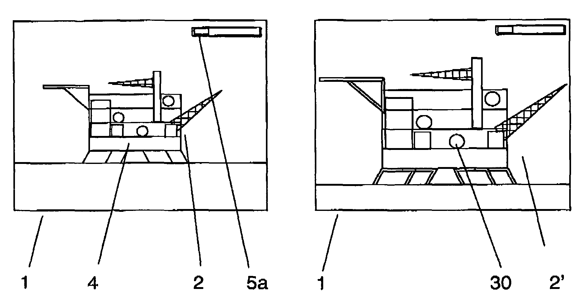
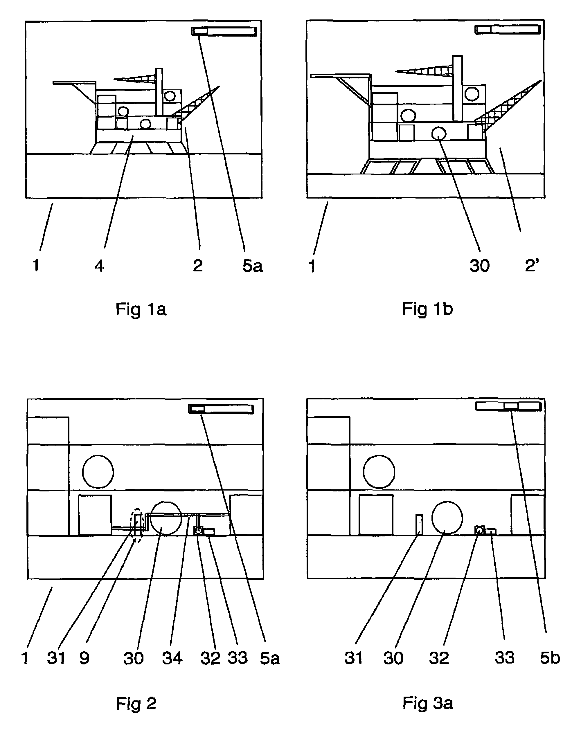
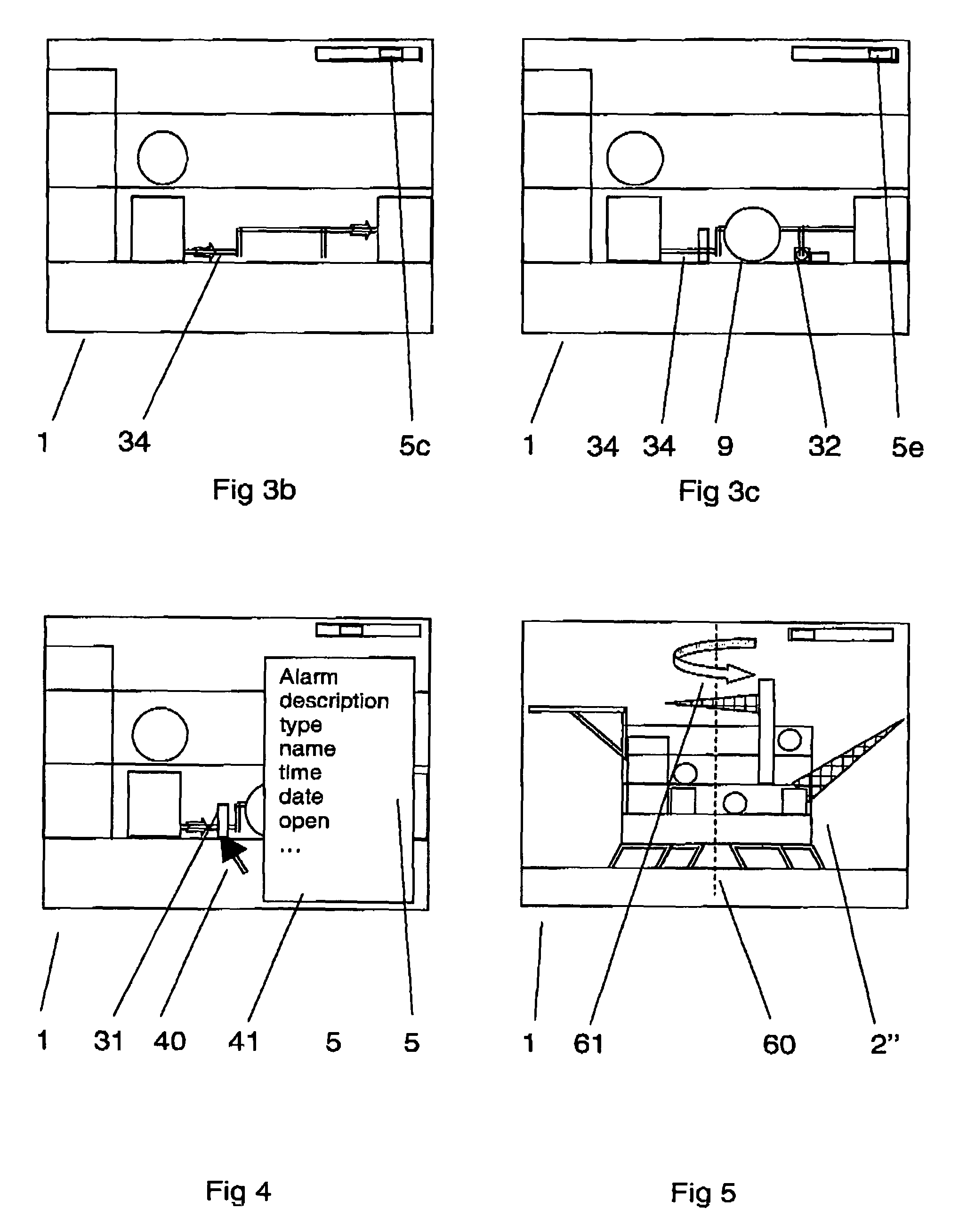
[0032]FIG. 1a shows display of an oil platform, a process for production or exploration etc for oil and gas. The display 1 comprises an oil platform 2, with one or more production areas 4, and a selection menu 5a. The display in this example is a 3-D model of an oil platform. The 3-D model displayed is a computer generated model that may be manipulated so that the oil platform may be viewed from different angles and at different resolutions or magnifications. FIG. 1b shows a close up view of the same model of the oil platform 2, and FIG. 2 shows a close up of process equipment on a part of the oil platform. FIG. 5 shows schematically that the 3-d model is rotatable, for example about an axis 60 in a direction indicated by arrow 60.

[0033]The process equipment of the oil platform is monitored and controlled by a control system. The control system comprises information about the process, each stage of the process, and each separate equipment in the process. The information, real time, ...


PUM


Abstract

A human-machine interface of a control system for monitoring and control of a process and including a computer generated model of the process. The process or a part or component of the process is displayed such that the model is arranged to map a point on the computer generated model to data held by the control system about the at least one part or component of the process. A method to monitor and control a process using the human-machine interface and a system including the interface are also described.

Description

CROSS-REFERENCE TO RELATED APPLICATIONS[0001]This application claims priority to U.S. provisional patent application 60 / 667,080 filed 1 Apr. 2005.TECHNICAL FIELD[0002]The present invention concerns a human machine interface for a system for control and / or monitoring of an industrial process, automated equipment or a device. The invention may be applied in many fields such as oil and gas, electricity generation, transmission, distribution as well as in industry. The invention may be applied to monitoring, control and / or programming of an industrial robot for robotic and automated applications.BACKGROUND ART[0003]A technician or a field operator, e.g. in a process plant, manufacturing installation, at off-shore oil and gas platform or at an electrical power transmission or distribution installation or substation, needs to check on alarms and other events reported by a control system, as well as interact with systems or devices in the installed equipment on a daily basis. An operator a...

Claims


Application Information

Patent Timeline
Patent Type & Authority Patents(United States)
IPC IPC(8): G05B15/02G06F3/048G05B23/02G05B15/00
CPCG05B17/02G05B23/0216G05B23/027G06F3/04815G06F3/04845G06F3/0481G06F2203/04806
Inventor SKOURUP, CHARLOTTEPRETLOVE, JOHNHUSOY, KRISTOFFER
Owner ABB (SCHWEIZ) AG
Why Eureka
Try Eureka