Safety interlock for control lines

a safety interlocking and control line technology, applied in the field of tubular strings, can solve the problems of accidental closing of slips around the control lines, affecting the safety of the control line, and difficult to locate the control line-engaging portion of the device precisely at the well center,

Inactive Publication Date: 2010-05-18
WEATHERFORD TECH HLDG LLC
View PDF71 Cites 8 Cited by
  • Summary
  • Abstract
  • Description
  • Claims
  • Application Information

AI Technical Summary

Benefits of technology

[0015]In yet another embodiment, a safety interlock system is provided to prevent the closing of the slips before the control line is pulled away from the tubular string.

Problems solved by technology

Because various pieces of equipment at and above well center are necessary to build a tubular string and the control line is being fed from a remotely located reel, getting the control line close enough to the tubular string to successfully clamp it prior to entering the wellbore is a challenge.
Because of that the control line-engaging portion of the device is difficult to locate precisely at well center.
The result is often a misalignment between the continuous control line and the tubular string making it necessary for an operator to manhandle the control line to a position adjacent the tubular before it can be clamped.
Another challenge to managing the control lines is the accidental closing of the slips around the control lines.
When the control line is near the tubular string, it is exposed to potential damage by the slips.
Thus, if the slips are prematurely closed, the slips will cause damage to the control line.

Method used


Image

  • Safety interlock for control lines
  • Safety interlock for control lines
  • Safety interlock for control lines

Examples


Embodiment Construction

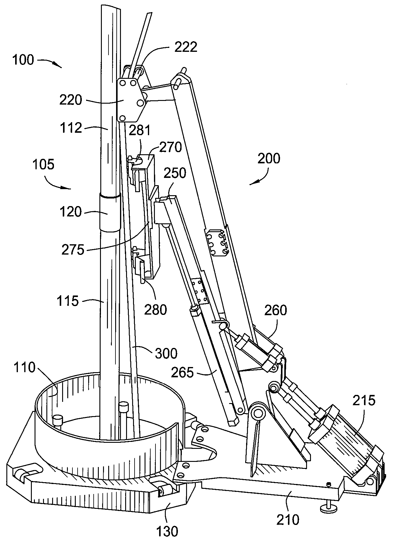
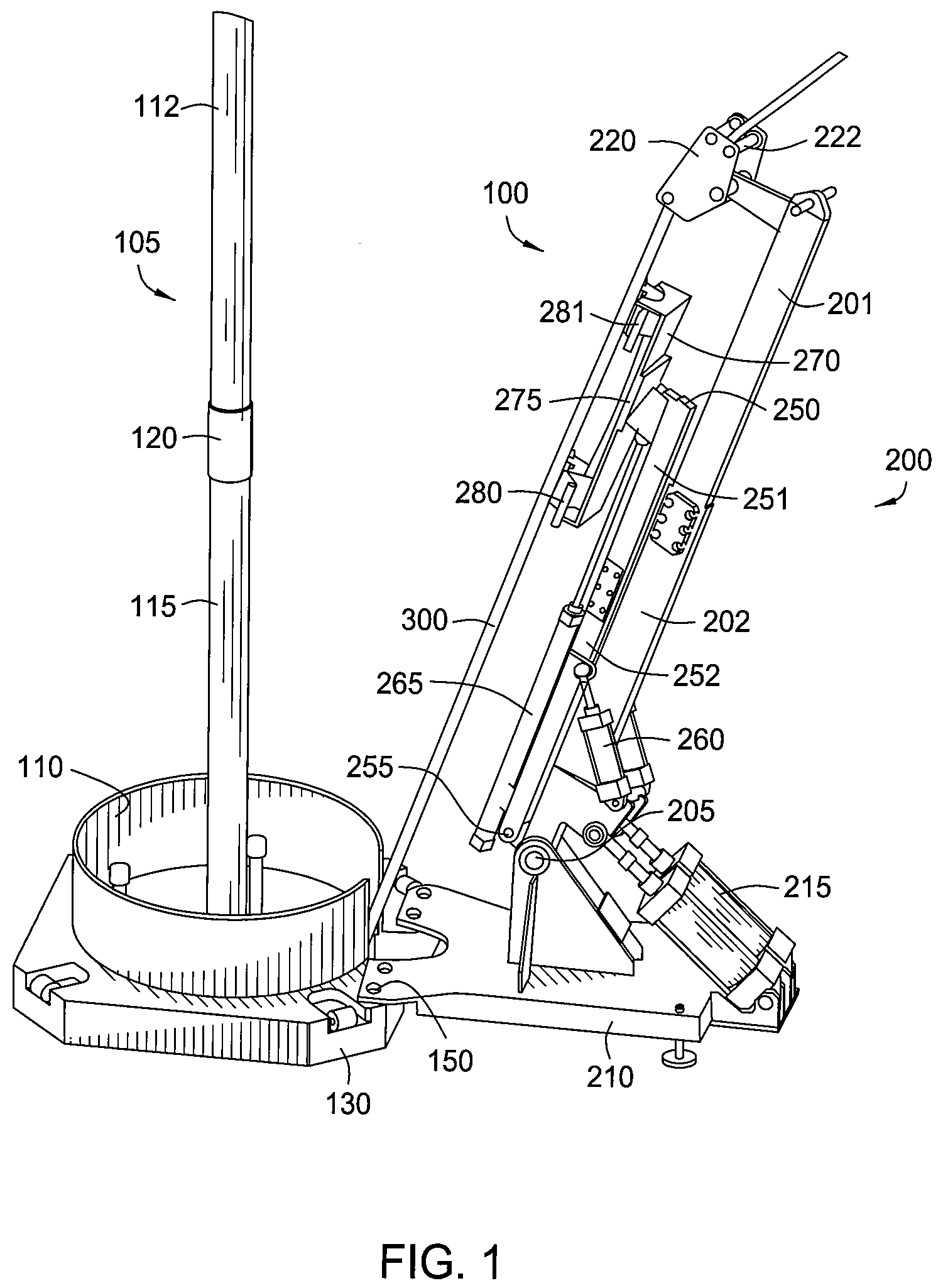
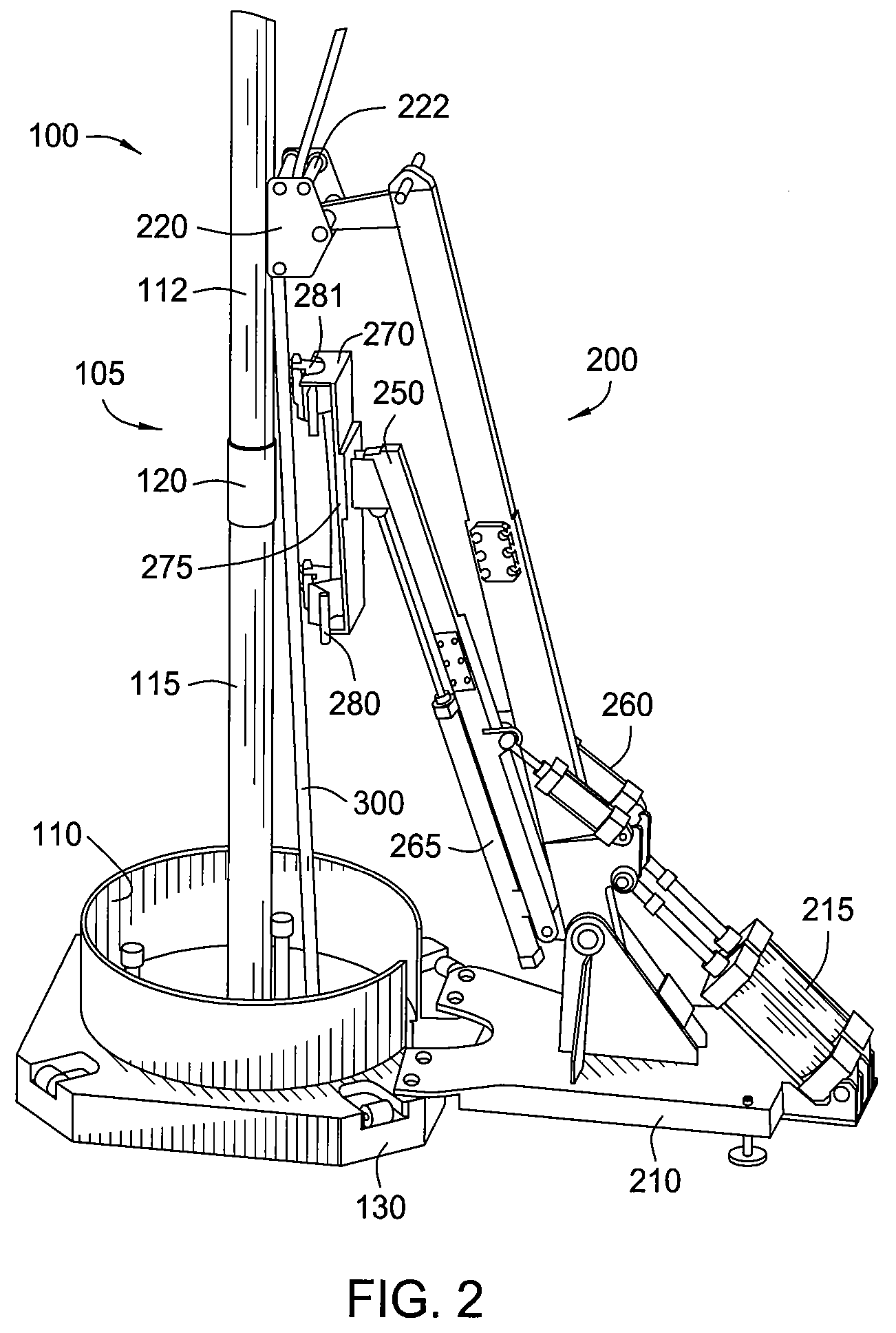
[0029]FIG. 1 illustrates one embodiment of an assembly 100 used to facilitate the clamping of a control line 300 to a tubular string 105. The assembly 100 is movable between a staging position and a clamping position. As shown, the assembly 100 is located adjacent the surface of a well 110. Extending from the well 110 is the tubular string 105 comprising a first 112 and a second 115 tubulars connected by a coupling 120. Not visible in FIG. 1 is a spider which consists of slips that retain the weight of the tubular string 105 at the surface of the well 110. Also not shown is an elevator or a spider which would typically be located above the rig floor or work surface to carry the weight of the tubular 112 while the tubular 112 is aligned and threadedly connected to the upper most tubular 115 to increase the length of tubular string 105. The general use of spiders and elevators to assemble strings of tubulars is well known and is shown in U.S. Publication No. US-2002 / 0170720-A1, which ...


PUM


Abstract

A protection tool is provided to protect a control line in a safe area while one or more slips of a spider are being closed. In another embodiment, a safety interlock system is provided to prevent the closing of the slips before the control line is pulled away from the tubular string. In yet another embodiment, a safety interlock system includes a safety interlock trigger adapted to be actuated by a protection tool. The safety interlock trigger is adapted to detect the physical presence of the protection tool, and thereafter send a signal to the interlock system to enable an operator or a control mechanism to safely close the slips.

Description

CROSS-REFERENCE TO RELATED APPLICATIONS[0001]This application claims benefit of co-pending U.S. Provisional Patent Application Ser. No. 60 / 740,849, filed on Nov. 30, 2005. This application is also a continuation-in-part of U.S. patent application Ser. No. 11 / 037,800, filed Jan. 18, 2005 now U.S. Pat. No. 7,249,637, which claims benefit of U.S. Provisional Patent Application Ser. No. 60 / 536,800, filed Jan. 15, 2004. Each of the aforementioned related patent applications is herein incorporated by reference in its entirety.BACKGROUND OF THE INVENTION[0002]1. Field of the Invention[0003]Embodiments of the present invention relate to the makeup of tubular strings at the surface of a well. More particularly, the invention relates to making up strings and running the strings into the well along with a control line or signal transmission line. More particularly still, the invention relates to methods and apparatus for facilitating the clamping of a control line or signal transmission line t...

Claims


Application Information

Patent Timeline
Patent Type & Authority Patents(United States)
IPC IPC(8): E21B19/12
CPCE21B19/16E21B17/1035
Inventor VOLD, GISLEABRAHAMSEN, EGILVESTERSJO, SVEIN EGILBAUSTAD, TERJESTOKKELAND, KAJHAUGEN, DAVID M.
Owner WEATHERFORD TECH HLDG LLC
Why Eureka
Try Eureka