
Image recording apparatus

a technology of image recording and recording sheet, which is applied in the direction of printing, power drive mechanisms, printing mechanisms, etc., can solve the problems of reducing the reliability of image data obtained by reading, undried ink on the recording sheet unfortunately adhering to the lower surface of the respective image sensor, and the accuracy of ejecting liquid to the recording sheet can be improved, less soiled, and high accuracy

Active Publication Date: 2010-05-18
BROTHER KOGYO KK
View PDF5 Cites 4 Cited by
  • Summary
  • Abstract
  • Description
  • Claims
  • Application Information

AI Technical Summary

Benefits of technology

[0007]In the ink-jet recording apparatus disclosed in Patent Document 1, lower surfaces of the respective image sensors are located below a height level of ejection surfaces of the respective recording heads. That is, the lower surfaces of the respective image sensors are located nearer to a belt for conveying the recording sheet than to the ejection surfaces of the respective recording heads. Thus, in both of a test pattern recording and a normal recording, ink mist tends to adhere to the lower surfaces (light-entering surfaces) of the respective image sensors. That is, the lower surfaces of the respective image sensors tend to be soiled. In addition, where the recording sheet is brought into contact with the lower surfaces of the respective image sensors due to jamming just after the inks have attached to the recording sheet, undried ink on the recording sheet unfortunately adheres to the lower surfaces of the respective image sensors. Where the inks have adhered to the lower surfaces of the respective image sensors, reliability of image data obtained by reading is lowered, so that unnecessary recovering operation is performed.
[0008]This invention has been developed in view of the above-described situations, and it is an object of the present invention to provide an image recording apparatus in which a lower surface of an image sensor that picks up an image recorded by recording heads is less soiled.
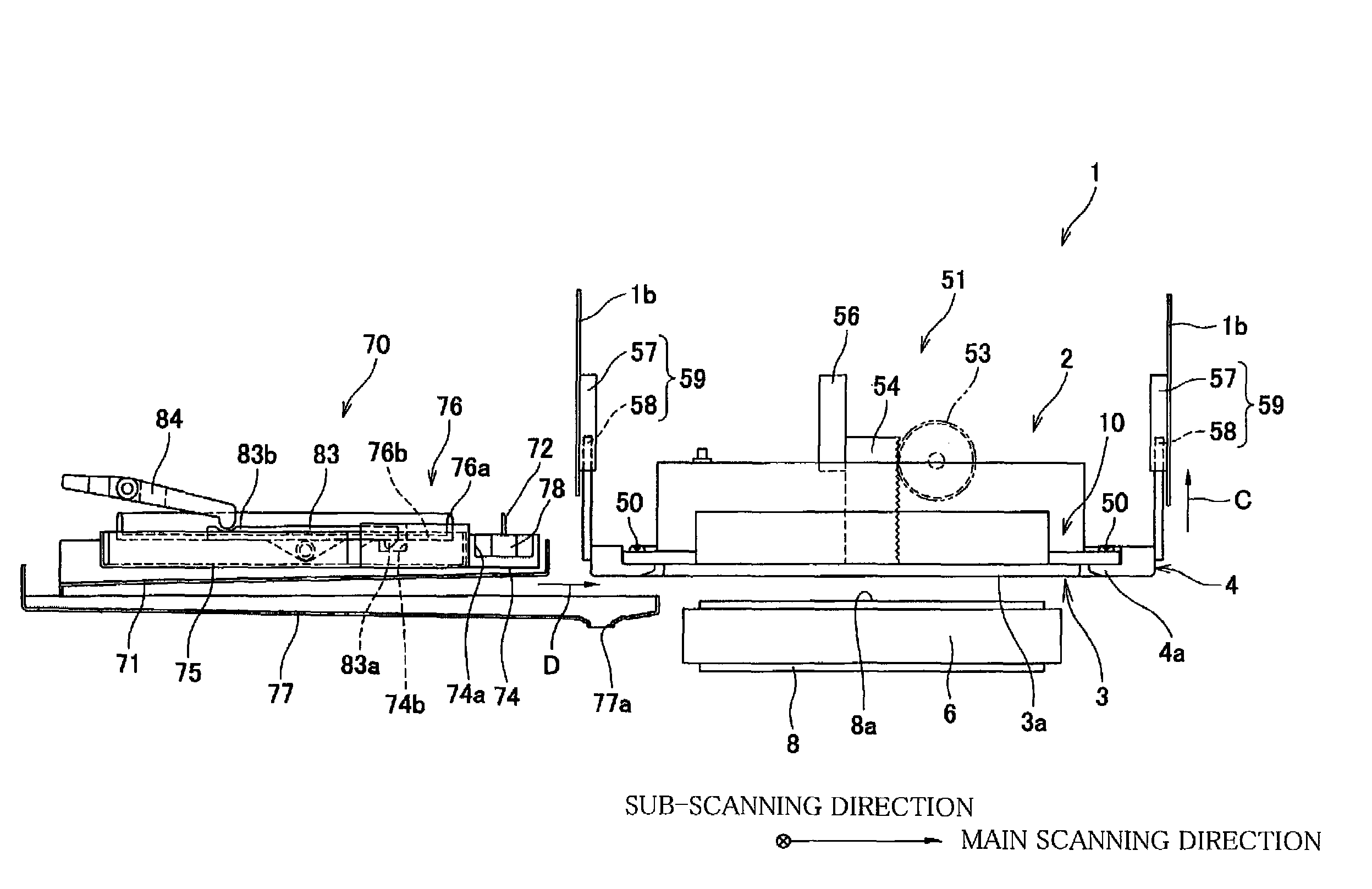
[0010]In the image recording apparatus constructed as described above, since the image sensor is moved upward and downward together with the recording head in a state in which the image sensor is more distant from the surface of the medium-convey belt than the recording head, the light-entering surface of the image sensor is less soiled. Further, when the liquid is ejected as a test in the inspecting mode, since the distance between the ejection surface and the medium-convey belt or the recording medium on the medium-convey belt is shorter than that in the normal recording mode, an ejected-liquid-attaching accuracy upon recording can be improved. In addition, the light-entering surface of the image sensor can be less soiled due to flying liquid mist. Furthermore, since the ejected-liquid-attaching accuracy upon the recording can be improved, a liquid ejection failure such as a non-ejection of the liquid from any of the ejection openings can be detected with a relatively high accuracy.

Problems solved by technology

That is, the lower surfaces of the respective image sensors tend to be soiled.
In addition, where the recording sheet is brought into contact with the lower surfaces of the respective image sensors due to jamming just after the inks have attached to the recording sheet, undried ink on the recording sheet unfortunately adheres to the lower surfaces of the respective image sensors.
Where the inks have adhered to the lower surfaces of the respective image sensors, reliability of image data obtained by reading is lowered, so that unnecessary recovering operation is performed.

Method used


Image

  • Image recording apparatus
  • Image recording apparatus
  • Image recording apparatus

Examples


Embodiment Construction

[0021]Hereinafter, there will be described a preferred embodiment of the present invention by reference to the drawings. It is to be understood that the following embodiment is described only by way of example, and the invention may be otherwise embodied with various modifications without departing from the scope and spirit of the invention.

[0022]General Structure of Ink-Jet Printer

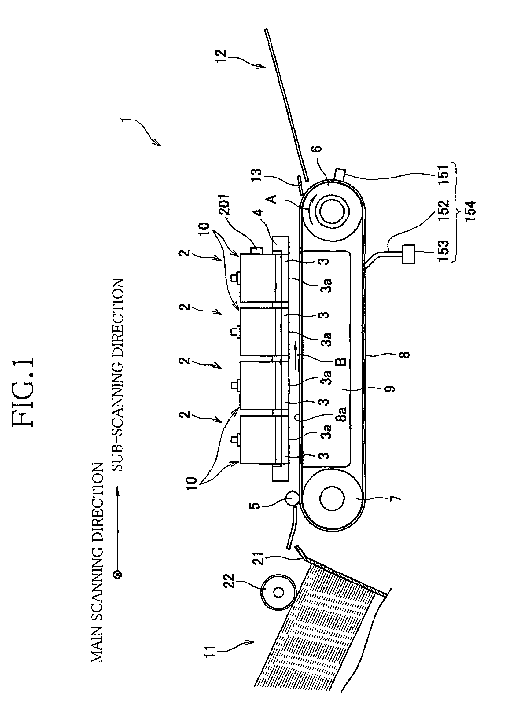
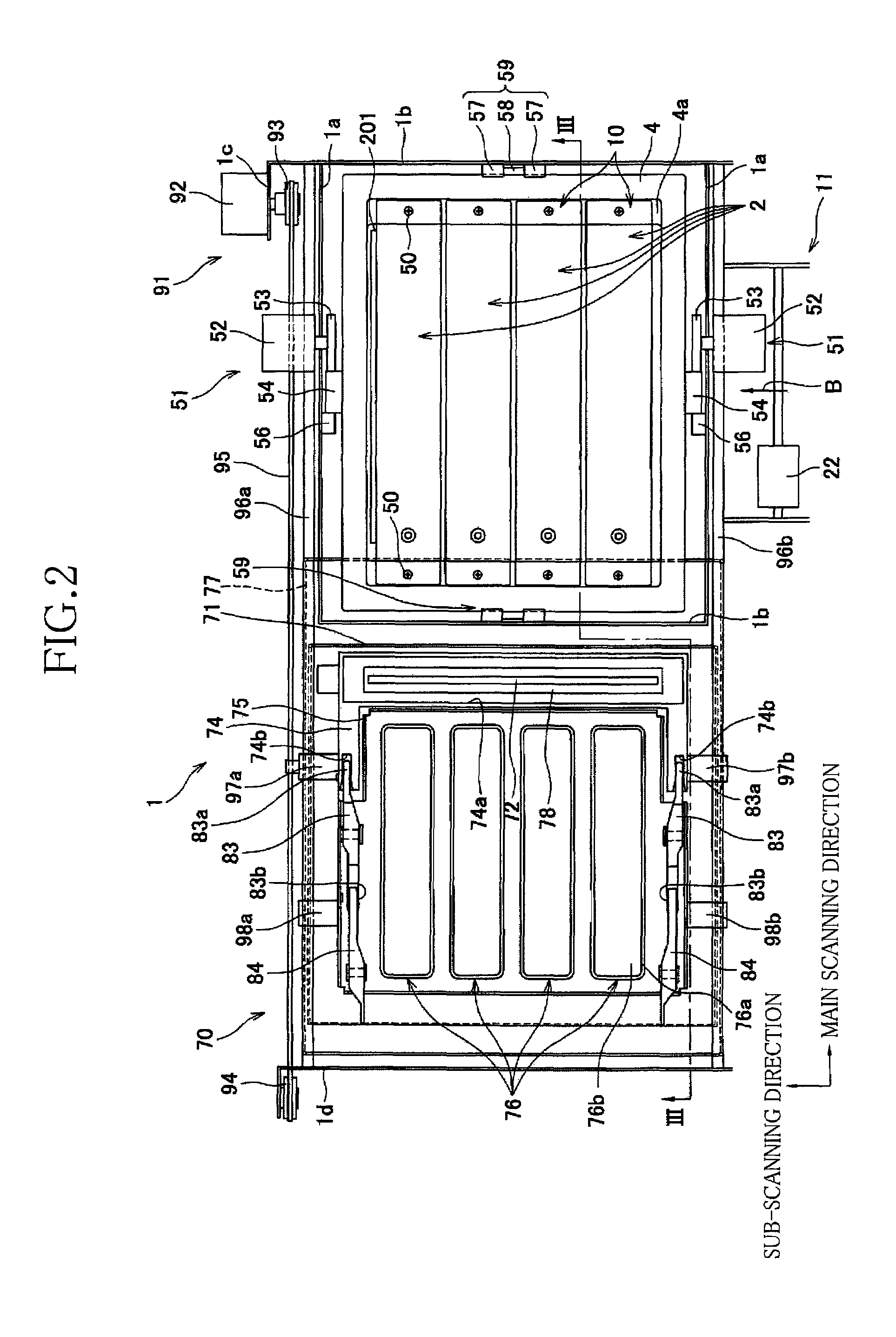
[0023]FIG. 1 shows an ink-jet printer 1 that is an image recording apparatus as an embodiment of the present invention. The ink-jet printer 1 is a color ink-jet printer having ink-jet heads 2 respectively ejecting inks (liquids) of four colors, namely, magenta, cyan, yellow, and black. The ink-jet printer 1 is provided with a sheet-supply mechanism 11 located at a left portion of FIG. 1 and a sheet-discharge portion 12 located at a right portion of FIG. 1.

[0024]In the ink-jet printer 1, there is formed a sheet-convey path through which a recording sheet as a recording medium is conveyed from the sheet-sup...


PUM


Abstract

An image recording apparatus including: a medium-convey belt; a recording head; an image sensor being movable together with the recording head and including an image-pickup element, an image-forming optical system, and a light-entering surface which is more distant from the medium-convey belt than an ejection surface of the recording head, and a raising and lowering mechanism which positions the recording head, wherein the recording head is positioned, when in an inspecting mode in which the recording head is inspected, at a first height at which an optical image of an image recorded on the medium-convey belt or recorded on the recording medium on the medium-convey belt is formed on the image-pickup element by the image-forming optical system, while positioned, when in a normal recording mode, at a second height at which the ejection surface is more distant from the medium-convey belt than at the first height, and wherein the image sensor picks up the image when the recording head is positioned at the first height.

Description

CROSS REFERENCE TO RELATED APPLICATION[0001]The present application claims priority from Japanese Patent Application No. 2007-270965, which was filed on Oct. 18, 2007, the disclosure of which is herein incorporated by reference in its entirety.BACKGROUND OF THE INVENTION[0002]1. Field of the Invention[0003]The present invention relates to an image recording apparatus configured to eject liquid to record an image on a recording medium, and more particularly to an image recording apparatus equipped with an image sensor which picks up a recorded image.[0004]2. Description of the Related Art[0005]Recently, there has been developed an ink-jet printer using a line head having a recording range larger than a width of a recording sheet as a recording medium. In such a line printer, recording for each extremely narrow portion of the recording sheet extending in a direction in which the recording sheet is conveyed is carried out only by a corresponding one of nozzles. Thus, even where there a...

Claims


Application Information

Patent Timeline
Patent Type & Authority Patents(United States)
IPC IPC(8): B41J25/308
CPCB41J25/308B41J11/007
Inventor ITO, KOJI
Owner BROTHER KOGYO KK
Learn More