Catheter for drainage of the bladder

Active Publication Date: 2010-05-18
SAUER MANFRED
View PDF30 Cites 19 Cited by
  • Summary
  • Abstract
  • Description
  • Claims
  • Application Information

AI Technical Summary

Benefits of technology

[0024]The tube and, if need be, the insertion aid could be made of a plastic material, such as PCV. In this connection, it will be of special advantage, when the tube and/or the insertion aid are chemically treated, in particular by means of plasticizers, so as to obtain constantly more flexible regions toward the free end. The treatment with plasticizers assists the manufacture of the catheter in that both the tube and, if need be, the insertion aid consist of PVC, and that both components are interconnected in a material engaging relationship by a mutual diffusion of plasticizers.
[0025]The arrangement of a spherical insertion aid requires special orifices to be able to take in body fluid. To this end, two or more orifices are provided in the tube. In a further advantageous manner, these orifices are formed directly behind the insertion aid. They are made, for example, by a punching operation. In a further advantageous man

Problems solved by technology

However, the known catheters for draining urine are problematic in practice, inasmuch as during the introduction of the catheter into the urethra and while guiding the catheter tip through the urethra into the bladder, it is necessary to overcome pockets, folds, bends, or the like.
If one pushes the catheter with a corresponding force against t

Method used


Image

  • Catheter for drainage of the bladder
  • Catheter for drainage of the bladder
  • Catheter for drainage of the bladder

Examples


Embodiment Construction

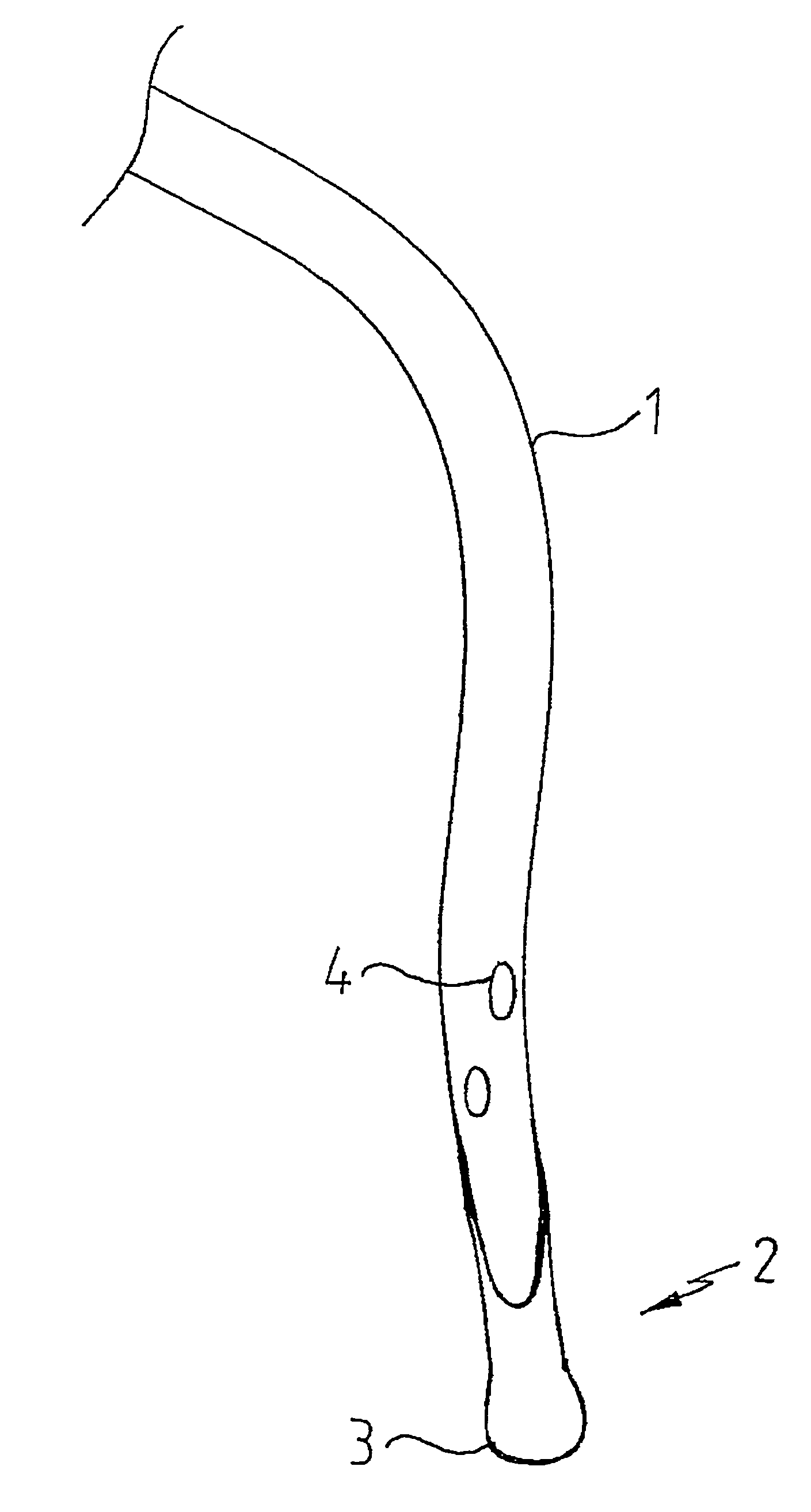
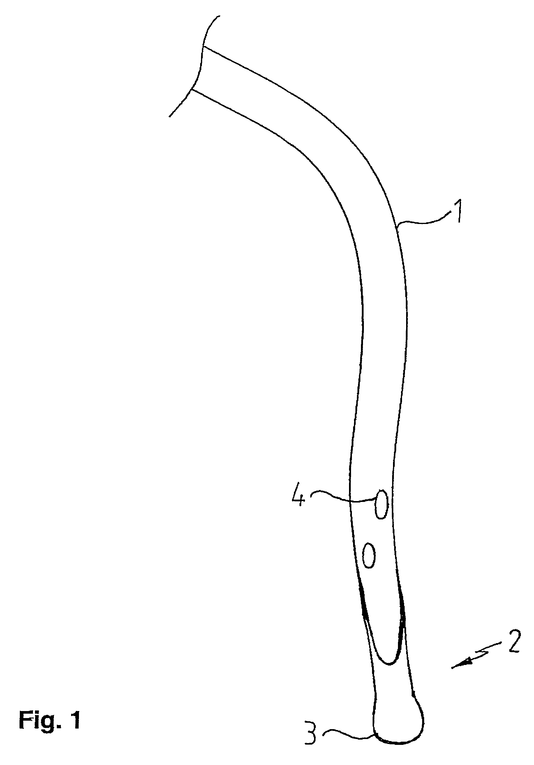
[0033]FIG. 1 illustrates an embodiment of a catheter according to the invention. For the sake of simplicity, the Figure shows only a flexible tube 1 with an insertion aid 2. The insertion aid 2 is arranged at the insertion end of the tube 1, and there secured to the tube 1. The insertion aid 2 is thus made integral with the tube 1, with the insertion aid 2 being substantially more flexible than the tube 1.

[0034]In accordance with the invention, the rear portion of the insertion aid 2 has essentially the same diameter as the tube 1, and connects accordingly to the tube 1 in a material engaging relationship. A head portion 3 of the insertion aid 2 is made rounded, i.e. spherical or ball-shaped, and has at least a slightly larger diameter than the diameter of the tube 1, which results in the above-described advantages.

[0035]As further shown in FIG. 1, the tube 1 includes orifices 4 for draining urine, with the selected embodiment comprising a total of two orifices 4. For a faster drain...


PUM


Abstract

A catheter for draining urine from the bladder and which is composed of a flexible plastic tube (1) having an insertion aid (2) secured to the insertion end of the tube. Thus the insertion aid and tube may be inserted into the urethra and guided therethrough into the bladder. The tube (1) has at least one orifice (4) in the region adjacent the insertion aid (2). Also, the insertion aid (2) connects with essentially the same diameter to the tube (1) and ends with a rounded head portion (3), whose diameter may be slightly larger than the diameter of the tube (1). The insertion aid may be significantly more flexible as compared to the tube.

Description

CROSS REFERENCE TO RELATED APPLICATION[0001]The present application is a continuation of international application PCT / DE03 / 00129, filed 17 Jan. 2003, and which designates the U.S. The disclosure of the referenced application is incorporated herein by reference.BACKGROUND OF THE INVENTION[0002]The invention relates to a catheter for draining urine from the bladder of a user, and which is composed of a flexible tube and an insertion aid secured to the insertion end of the tube for inserting it into the urethra and guiding it therethrough into the bladder, and with the tube having at least one orifice in the region adjacent the insertion aid.[0003]The invention further relates to a catheter for draining urine which is composed of a flexible tube for inserting it into the urethra and guiding it therethrough into the bladder, with the tube being made of plastic and having at least one orifice adjacent its insertion or free end or in the region preceding the free end.[0004]For managing i...

Claims


Application Information

Patent Timeline
IPC IPC(8): A61M5/00A61M1/00A61M27/00A61M25/00
CPCA61M25/0054A61M25/0069A61M25/0068A61M25/0017A61M2210/1085A61M25/008
Inventor SAUER, MANFRED
Owner SAUER MANFRED
Why Eureka
Try Eureka