
Network element architecture for deep packet inspection

a network element and deep packet inspection technology, applied in the field of computer networking, can solve the problems of inability to change the subscriber policy in real-time, link(s) b>112/b> can get overloaded, and not provide enough bandwidth for bandwidth sensitive services,

Active Publication Date: 2010-05-18
TELLABS COMM CANADA
View PDF55 Cites 197 Cited by
  • Summary
  • Abstract
  • Description
  • Claims
  • Application Information

AI Technical Summary

Benefits of technology

"The patent describes a system for shaping traffic in a network. It consists of a set of line cards and processor cards that are connected through a full mesh communication infrastructure. Each line card has a physical interface and a set of policy network processors that inspect and shape incoming traffic. The processor cards also have policy generating processors. The system generates statistics based on the incoming traffic and uses them to update traffic shaping policies in real-time. The technical effect of this invention is an efficient and flexible way to shape traffic in a network, which can improve performance and reliability."

Problems solved by technology

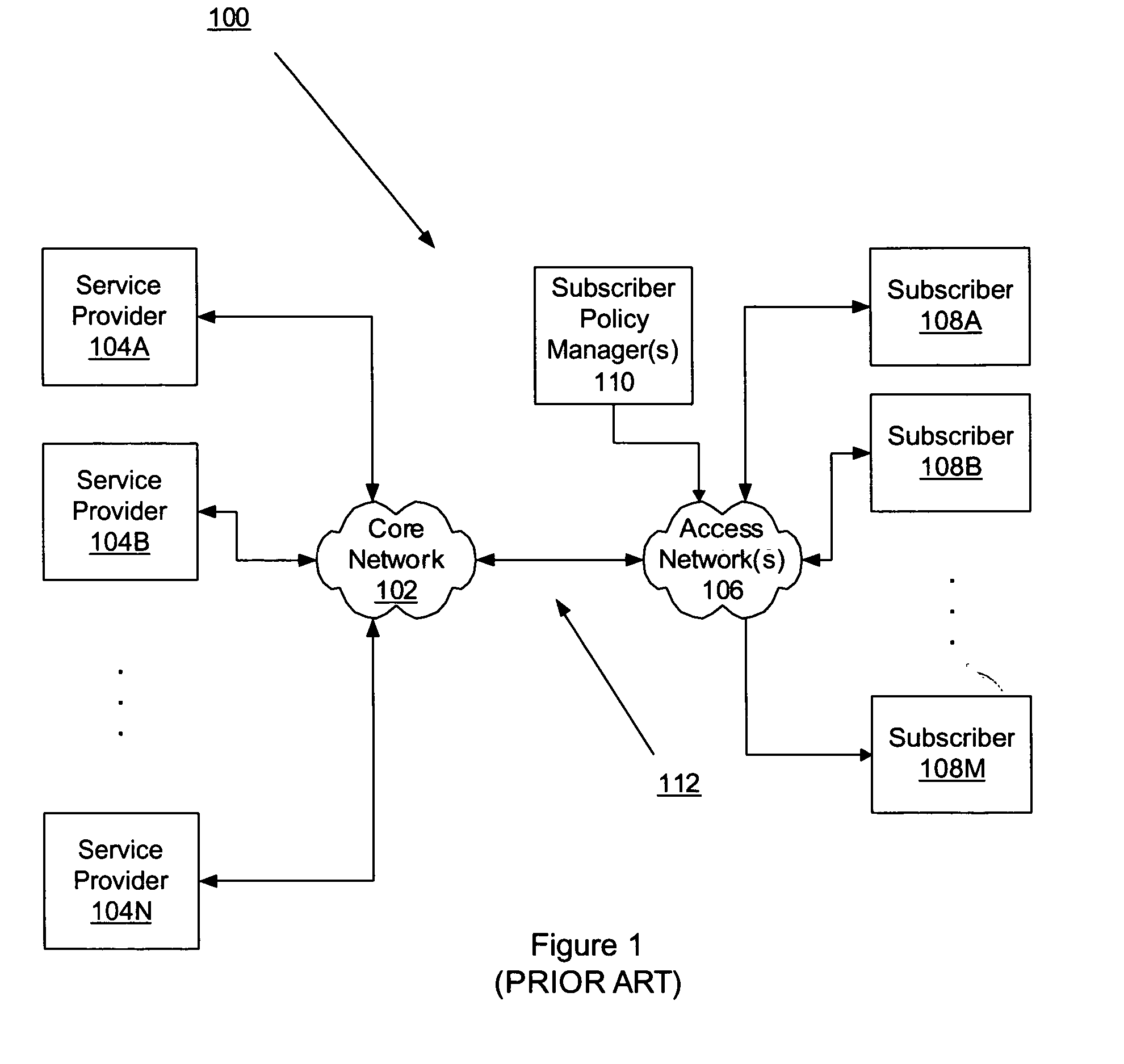
However, because each access network 106 can support thousands of subscribers, link(s) 112 can get overloaded and not provide enough bandwidth for these bandwidth sensitive services.
Subsequently, the quality of these services degrades or becomes interrupted altogether.
Although existing traffic shapers are subscriber aware, these traffic shapers only enforce pre-determined subscriber policies.
This does not allow subscriber policies to change in real-time based on existing network conditions.
Furthermore, existing traffic shapers cannot handle the high volume of data traffic that cross the core 102 and access 116 networks.
However, flow switches have limited data traffic processing capability, are not subscriber aware, perform limited or no deep packet inspection, and cannot update subscriber policies in real-time.

Method used


Image

  • Network element architecture for deep packet inspection
  • Network element architecture for deep packet inspection
  • Network element architecture for deep packet inspection

Examples


Embodiment Construction

[0035]In the following description, numerous specific details such as application subscriber data traffic flow, traffic policy, data packet, processor card, line card, deep packet inspection and interrelationships of system components are set forth in order to provide a more thorough understanding of the invention. It will be appreciated, however, by one skilled in the art that the invention may be practiced without such specific details. In other instances, control structures, gate level circuits and full software instruction sequences have not been shown in detail in order not to obscure the invention. Those of ordinary skill in the art, with the included descriptions, will be able to implement appropriate functionality without undue experimentation.

[0036]References in the specification to “one embodiment”, “an embodiment”, “an example embodiment”, etc., indicate that the embodiment described may include a particular feature, structure, or characteristic, but every embodiment may ...


PUM


Abstract

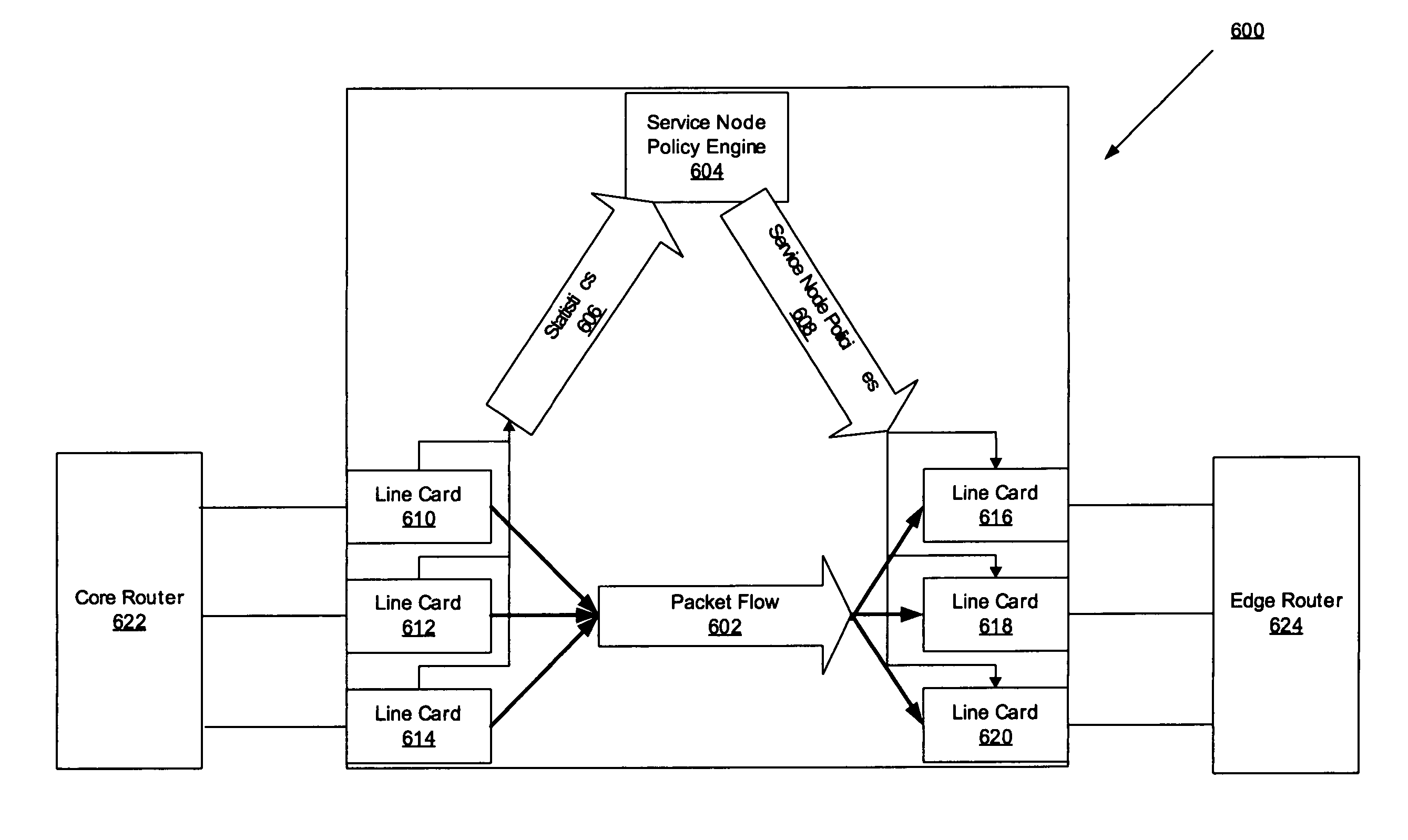
A method and apparatus for an application aware traffic shaping service node architecture is described. One embodiment of the invention, the service node architecture includes a set of one or more line cards, a set of one or more processor cards and a full mesh communication infrastructure coupling the sets of line and processor cards. Each link coupling the sets of line and processor cards is of equal capacity. A line card includes a physical interface and a set of one or policy network processors, with the network processors performing deep packet inspection on incoming traffic and shaping outgoing traffic. Processors cards include a set of one or more policy generating processors. According to another embodiment of the invention, the service node generates a set of statistics based on the incoming traffic and continually updates, in real-time, traffic shaping policies based on the set of statistics.

Description

CROSS-REFERENCE TO RELATED APPLICATIONS[0001]This patent application is related to the co-pending U.S. Patent Application, entitled AN APPLICATION AWARE TRAFFIC SHAPING SERVICE NODE POSITIONED BETWEEN THE ACCESS AND CORE NETWORKS, Ser. No. 11 / 106,163 filed on Apr. 13, 2005.BACKGROUND[0002]1. Field[0003]Embodiments of the invention relate to the field of computer networking; and more specifically, to shaping data traffic in a computer network.[0004]2. Background[0005]A modern metro area network 100 is composed of two types of networks: a core network 102 and one of more access networks 106. The core network 102 communicates data traffic from one or more service providers 104A-104N in order to provide services to one or more subscribers 108A-108M. Services supported by the core network 102 include, but are not limited to, (1) a branded service, such as a Voice over Internet Protocol (VoIP), from a branded service provider; (2) a licensed service, such as Video on Demand (VoD), through...

Claims


Application Information

Patent Timeline
Patent Type & Authority Patents(United States)
IPC IPC(8): H04L12/26H04L12/56
CPCH04L47/20H04L43/08H04L47/10H04L41/0896H04L41/0213H04L41/046H04L47/43
Inventor LUFT, SIEGFRIED JOHANNESCHIANG, PING
Owner TELLABS COMM CANADA
Learn More