Dual bevel table and slide miter saw

a table saw and slide technology, applied in the field of combination table saws, can solve the problems of incompatibility with operator accustomed procedures, limited rip cut width, manual control of prior art table saw slide cutting, etc., and achieves the effect of maximizing the performance of the applied hardware dimension, improving stationary cutting performance, and increasing cos

Inactive Publication Date: 2010-05-25
GAW STANLEY E
View PDF8 Cites 34 Cited by
  • Summary
  • Abstract
  • Description
  • Claims
  • Application Information

AI Technical Summary

Benefits of technology

[0010]It is further an object of this invention to provide better stationary cutting performance than known prior art slide miter saws. To this end, a cutting envelope is provided that maximizes performance for the applied hardware dimensions.
[0011]It is stiff further an object of this invention to provide a stationary workpiece cutting action that is directed away from the operator as is provided by the popular prior art over-platform slide miters. This cutting action is also to provide a cut initiation point that is located at the platform surface, conveniently visible to the operator, and that normally coincides with a standard workpiece marking edge. This provides the convenience of a laser line without the added cost.
[0013]It is further an object of this invention to provide a bevel locking means that simultaneously locks two points, one at each first and second sides of the cradle, to the frame, to maintain a more rigid configuration.

Problems solved by technology

Radial arm saws provide both functions, and have been commercially successful; however, their size and weight make them non transportable, and their rip cut widths are limited.
Examples of these designs include U.S. Pat. No. 5,357,834 issued to Ito et al. entitled “Miter Saw”; U.S. Pat. No. 5,720,213 issued to Sberveglieri entitled “Bevel Table Saw Adjustment”; and U.S. Pat. No. 6,591,725 issued to Martin entitled “Circular Sawing Machine.” However, the prior art has not developed a table saw with slide miter cutting capabilities that is competitive with the prior art above platform slide miter saws Further, the manual control of prior art table saw slide cutting, is not compatible with operator accustomed procedures.

Method used


Image

  • Dual bevel table and slide miter saw
  • Dual bevel table and slide miter saw
  • Dual bevel table and slide miter saw

Examples


Embodiment Construction

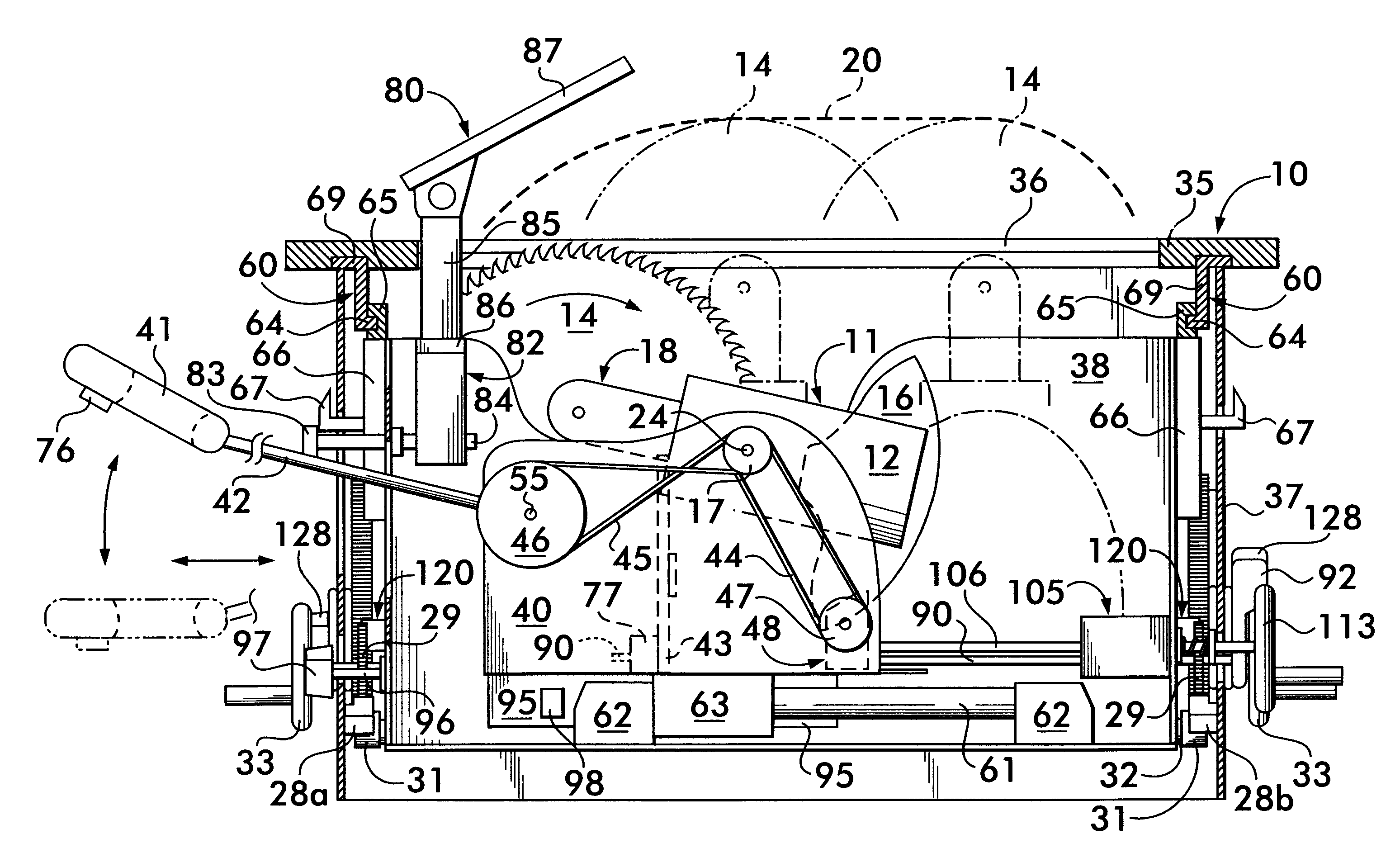
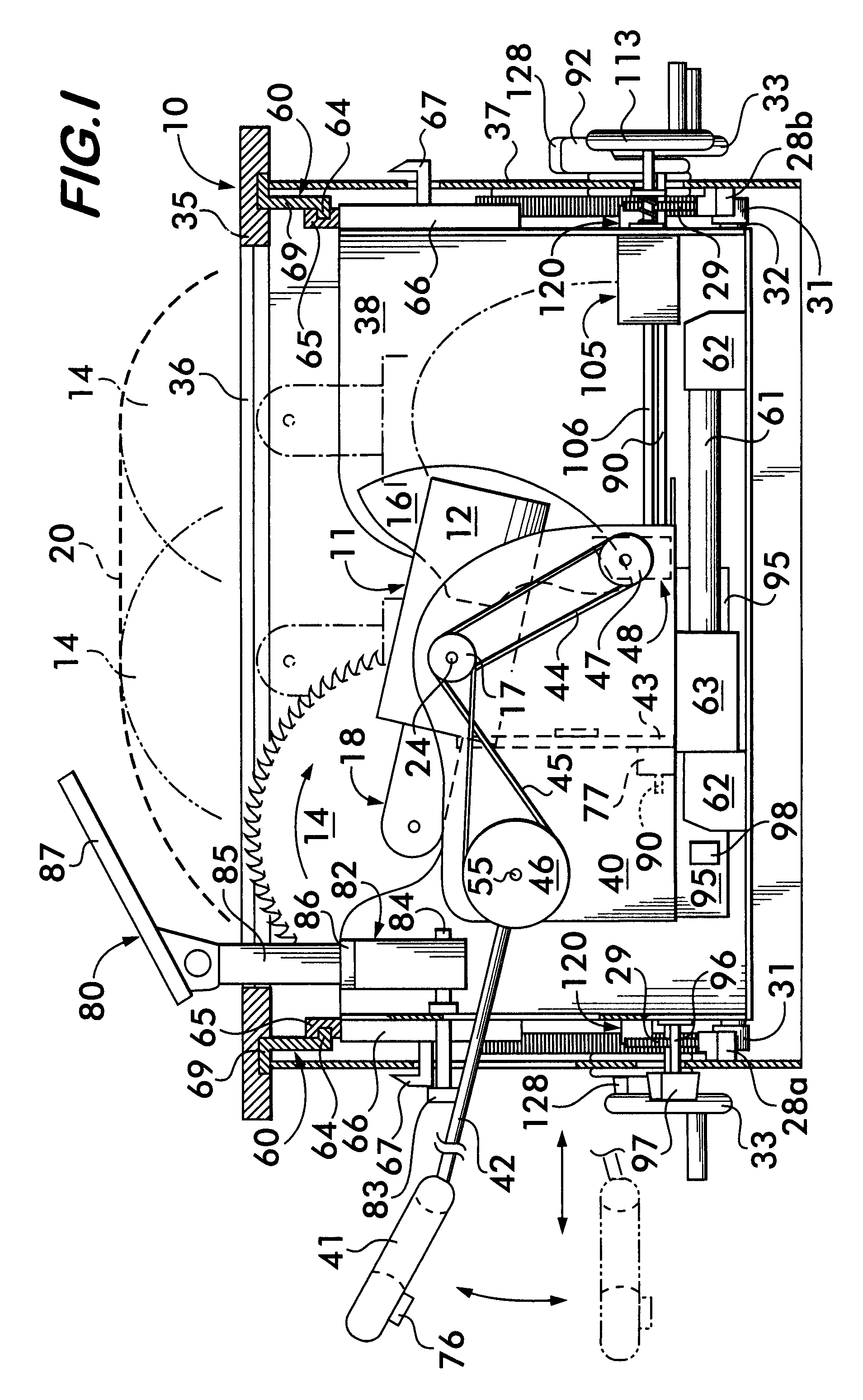
[0024]With reference to the drawings, in which common components have been numbered the same, FIG. 1 illustrates in one embodiment, a double bevel combination table saw and slide miter saw 10, comprising a frame 37, and having a working platform 35 in which is formed a saw slot 36. The saw may be operated as a slide miter saw from a first side of the platform 35 (the left side of this figure), herein referred to as “the miter mode side”, or operated as a conventional table saw from the opposing side of the platform 35 (the right side of this figure), herein referred to as “the table mode side”. These opposing sides are at opposite ends of the slot 36. Referring to FIG. 5, a pivot axis 15 for the bevel action of this invention, is established as a line substantially on the surface of platform 35 and coincident with the longitudinal center line of slot 36.

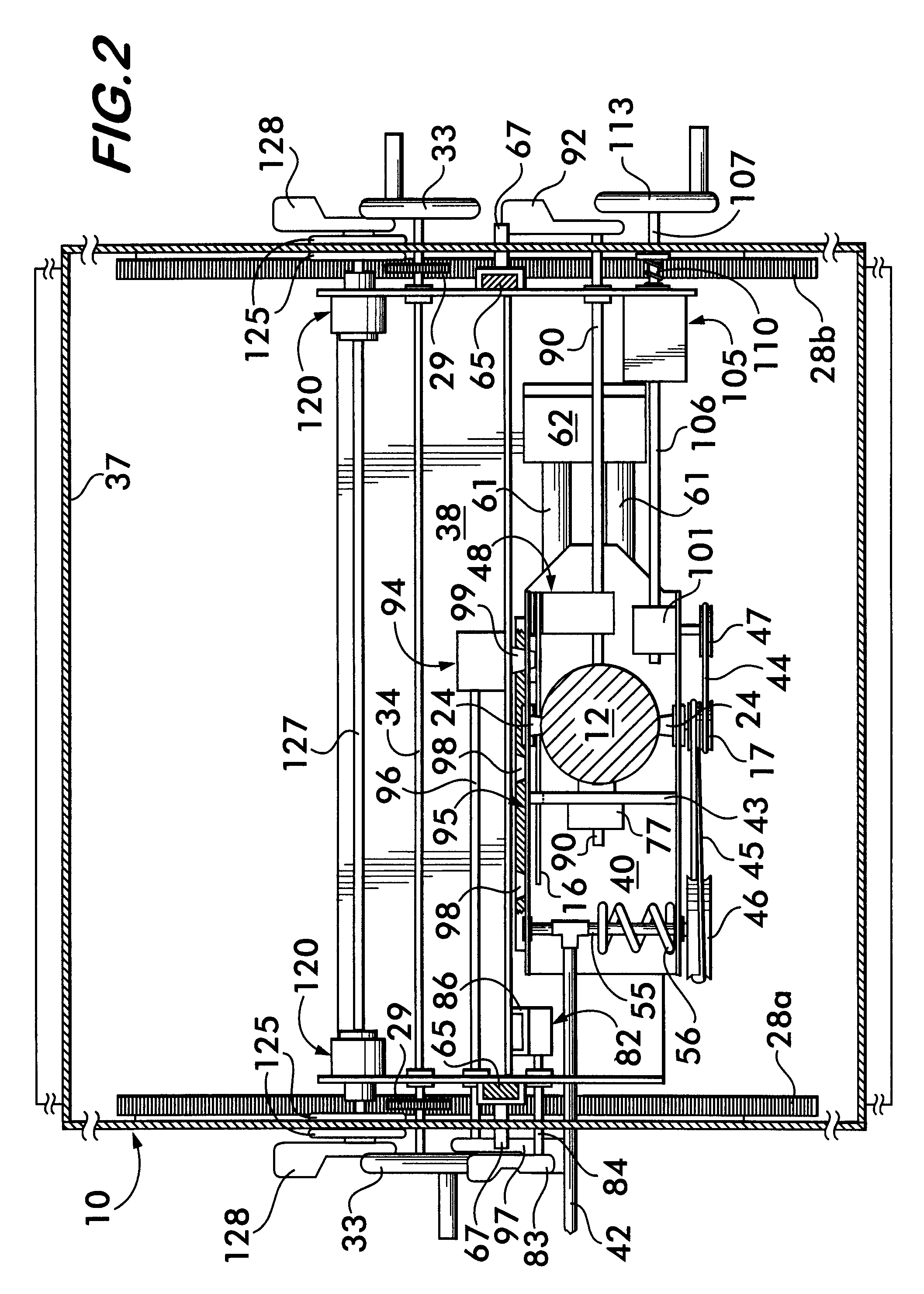
[0025]Referring to FIGS. 1, 2, and 3, a supporting cradle 38, disposed beneath platform 35, is the framework on which a saw assembl...


PUM

PropertyMeasurementUnit
tilt angleaaaaaaaaaa
anglesaaaaaaaaaa
slide distancesaaaaaaaaaa

Abstract

A portable, double bevel, combination table saw and slide miter saw comprising a horizontally disposed working platform with an elongated slot, is supported by a frame. A saw assembly is pivotably mounted beneath the working platform, with a saw blade that protrudes through the slot to cut a workpiece on the platform whereby stationary workpiece operations as well as moving workpiece operations may be executed. The stationary workpiece operations are executed from one side of the platform, and moving workpiece operations are executed from the opposite side of the platform, with separate appropriate controls on each side. The possibility of interference between saw assembly parts and the underside of the work platform inherent in double bevel configurations is avoided by the self-adjustment of the maximum depth for the workpiece bevel cuts.

Description

FIELD OF THE INVENTION[0001]The present invention relates to a portable combination table saw. More specifically, it relates to a table saw wherein moving workpiece cutting, stationary workpiece cutting, and double beveling capabilities are provided in one device.BACKGROUND OF THE INVENTION[0002]For transportable personal or contractor use, there has been a steady progression of designs of bench saws. For moving work pieces, these range from simple single position saw blade table saws to beveling and depth cut adjustable table saws. The operational advantage of having stationary workpiece cross cutting was recognized early in design of bench saws, with the ensuing design of swinging saws and sliding saws having motors either above or below the work platform. Comprehensive designs such as radial arm saws and above the work platform slide miter saws have found recent popularity.[0003]Another portable saw design is a saw that achieves long moving workpiece rip cutting, and also provide...

Claims


Application Information

Patent Timeline
Patent Type & Authority Patents(United States)
IPC IPC(8): B27B5/00
CPCB23D45/066B23D45/067Y10T83/7697Y10T83/8773Y10T83/7705Y10T83/773
Inventor GAW, STANLEY E.
Owner GAW STANLEY E
Why Eureka
Try Eureka