Automatic suction structure of a vacuum container

a vacuum container and automatic technology, applied in the direction of liquid handling, packaging goods, transportation and packaging, etc., can solve the problems of poor air suction effect, time-consuming and laborious assembly, and problems such as prior art structure, and achieve the effect of simple structure, easy operation and simple structur

Inactive Publication Date: 2010-05-25
CHOU MING SHI
View PDF8 Cites 15 Cited by
  • Summary
  • Abstract
  • Description
  • Claims
  • Application Information

AI Technical Summary

Benefits of technology

[0011]There are shortcomings in the prior art as discussed herein. The present invention is a suction structure of a vacuum container 90 comprising a pumping unit 60, power supply 50, vacuum releaser 80 and a vacuum detector 70. Thus, container 90 allows for automatic air suction, automatic detection, safety power disconnection, continuous vacuuming, as well as easy operation. Another benefit of the present invention is that the suction pump 63 extracts air in the container via a suction pipe 61 and a check valve 62, thereby achieving easy operation with a simple structure.

Problems solved by technology

However, since it is difficult for a vacuum pump to maintain air tightness with the container during the actual sealing and operation, the air suction effect is often poor, or leads to failure due to air leakage.
Problems are found from such a prior art structure during actual application.
First, due to complexity of the air extractor structure and assembly procedure of deceleration gear set 2 and coupled actuating arm 3, the assembly requires a time-consuming and tedious process.
Time is wasted and costs the favor of the operators.
Since the air extractor is equipped with continuously-running deceleration gear sets 2, the swinging motion of gear sets will lead to defects in the air extractor 8.

Method used


Image

  • Automatic suction structure of a vacuum container
  • Automatic suction structure of a vacuum container
  • Automatic suction structure of a vacuum container

Examples


Embodiment Construction

[0026]The features and the advantages of the present invention will be more readily understood upon a thoughtful deliberation of the following detailed description of a preferred embodiment of the present invention with reference to the accompanying drawings.

[0027]FIGS. 3-13 depict preferred embodiments of an automatic suction structure of vacuum container of the present invention, which are provided only for explanatory purposes.

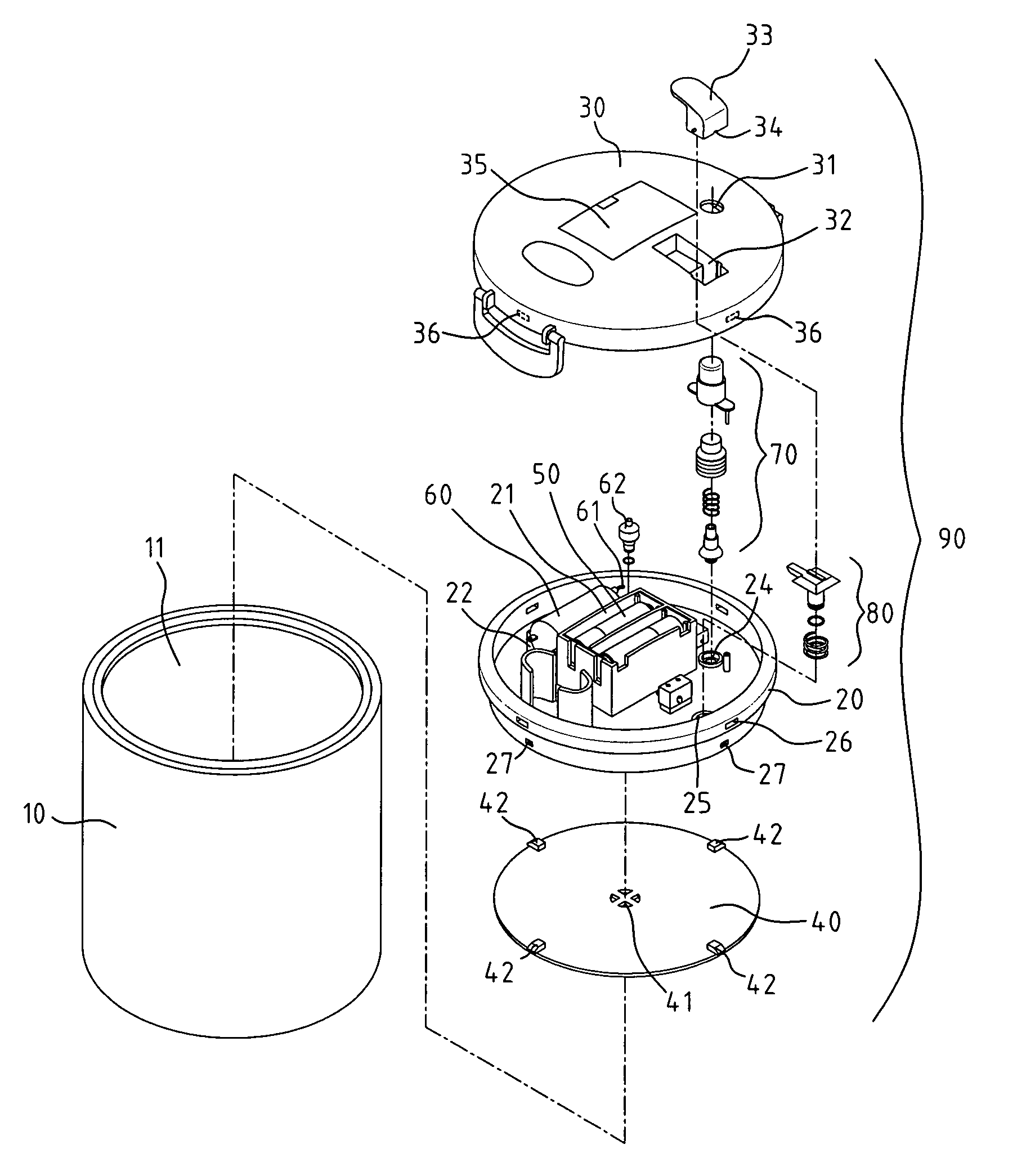
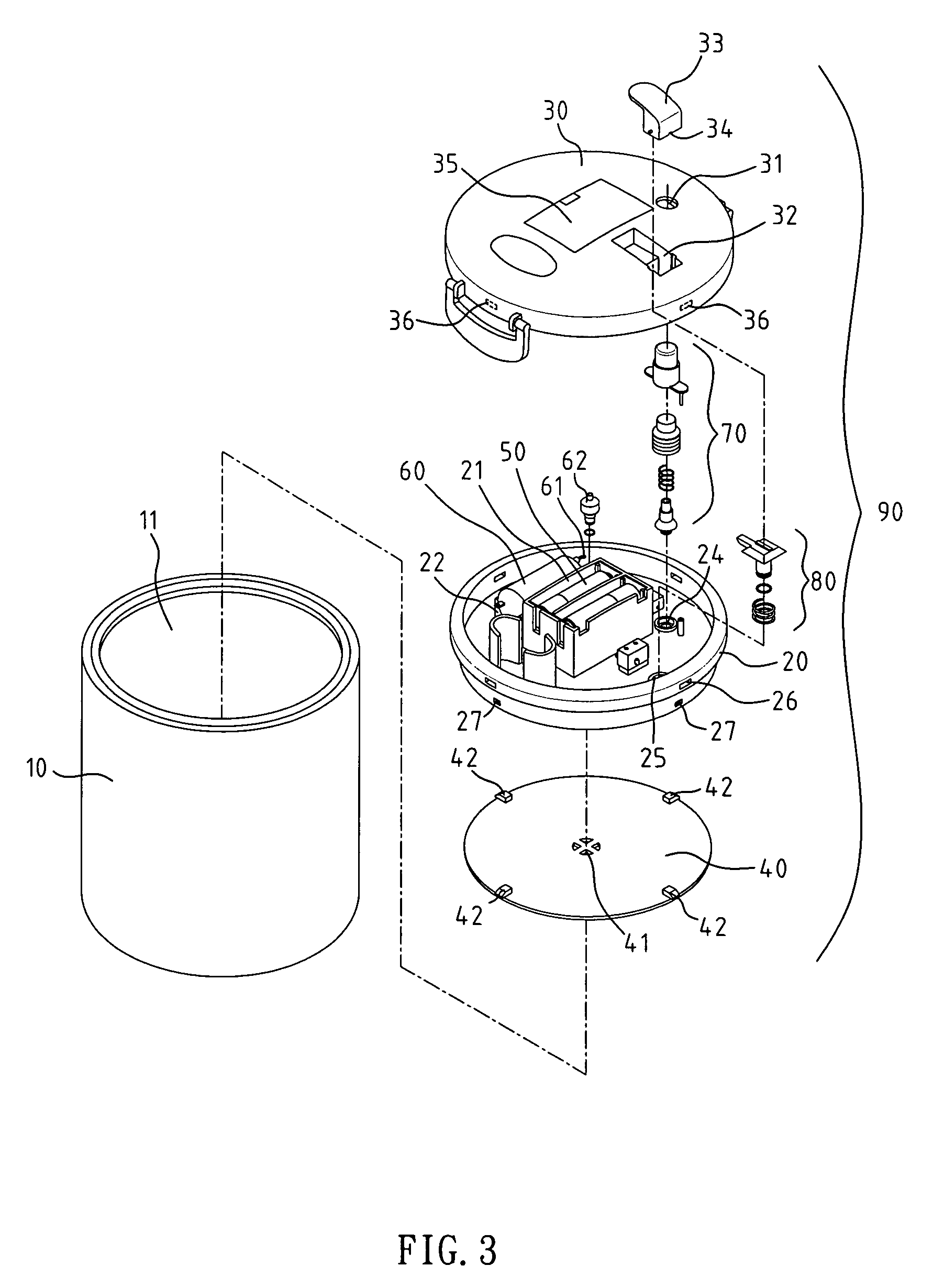
[0028]As shown in FIGS. 3, 4, 9, the present invention comprises a vacuum container 10, which has an open end 11 facing upwards.

[0029]There is a container 90, which is comprised of a middle container 20, an upper container 30 and a lower plate 40. The container 90 is mounted into open end 11 of vacuum container 10. A power supply fixer 21 is placed at a preset location of middle container 20, and a suction pump fixer 22 is placed at the other side. A suction hole 23 is placed at one side of suction pump fixer 22, as shown in FIG. 9. A discharge hole 25 and ...


PUM

PropertyMeasurementUnit
vacuum pressureaaaaaaaaaa
flexibleaaaaaaaaaa
pressureaaaaaaaaaa

Abstract

The present invention provides an improved automatic suction structure of a vacuum container. The structure includes a pumping unit, a power supply, a vacuum releaser and a vacuum detector. The structure allows for automatic air suction, automatic detection, safety power disconnection and continuous vacuuming as well as easy operation. The present invention guarantees improved quality and convenient operation.

Description

RELATED U.S. APPLICATIONS[0001]Not applicable.STATEMENT REGARDING FEDERALLY SPONSORED RESEARCH OR DEVELOPMENT[0002]Not applicable.REFERENCE TO MICROFICHE APPENDIX[0003]Not applicable.FIELD OF THE INVENTION[0004]The present invention relates generally to an improved automatic suction structure of a vacuum container, and more particularly to an automatic suction structure of vacuum container which comprises of a power supply, a pumping unit, a vacuum detector and a vacuum releaser. The container allows for automatic air suction, automatic detection, safety power disconnection and continuous vacuuming as well as easy operation.BACKGROUND OF THE INVENTION[0005]Conventional airtight containers are commonly used to accommodate food products or precision devices. While a vacuum pump extracts air from the container via a one-way valve, a negative pressure for reliable adsorption of container is formed. However, since it is difficult for a vacuum pump to maintain air tightness with the conta...

Claims


Application Information

Patent Timeline
Patent Type & Authority Patents(United States)
IPC IPC(8): B65B31/04
CPCB01J3/03B01J3/006
Inventor TSAY, SHIU-CHU
Owner CHOU MING SHI
Why Eureka
Try Eureka