Power drive nailing machine

a power drive and nailing machine technology, applied in the direction of nailing tools, manufacturing tools, stapling tools, etc., can solve the problems of power drive nailing machines that cannot be activated or operated erroneously, and cannot carry out adjusting operations in an operation above an unstable foothold, so as to prevent an erroneous operation and facilitate operation

Active Publication Date: 2010-05-25
MAX CO LTD
View PDF26 Cites 6 Cited by
  • Summary
  • Abstract
  • Description
  • Claims
  • Application Information

AI Technical Summary

Benefits of technology

[0007]One or more embodiments of the invention provide a nailing machine including a strike depth adjusting apparatus capable of easily operating to adjust a length of projecting a contact member from a front end of a nose portion without needing a tool, further, capable of preventing an erroneous operation brought about by deforming a contact arm by transmitting movement of the contact member along the nose portion directly to an activation control apparatus.
[0021]According to one or more embodiments of the invention, there is formed the guide hole provided at the side face portion of the nose portion to be substantially in parallel with injection port, the contact rod substantially in a straight shape is supported by the guide hole slidably and rotatably by being inserted into the guide hole, the side of the upper end portion of the contact rod is connected to the activation control apparatus and the side of the lower end portion thereof is screwed to be connected to the contact member. Therefore, when the power drive nailing machine is started, sliding movement of the contact member operated by the struck member is linearly transmitted to the contact rod, and the contact rod is operated to slide in parallel with the injection port of the nose portion to operate the activation control apparatus. As a result, the power drive nailing machine can firmly be activated. Further, according to such a contact rod, a part thereof can be fabricated without hardly working an outer shape or the like by using, for example, a material on sale having a hexagonal section and therefore, a significant reduction in cost can be achieved.
[0022]Further, there is provided the operating dial rotatably provided integrally with the contact rod by being penetrated to be inserted slidably by the contact rod and restricted from being moved in the up and down direction rotatably by the nose portion, and the length of projecting the contact member in a direction of the front end of the nose portion is variably adjusted by rotating the contact rod by way of the operating dial. Therefore, when the operating dial is operated to rotate in order to adjust the strike depth, the operating dial can be operated to rotate always at a constant portion without moving the operating dial in the axial direction and therefore, the strike depth can easily be operated to adjust.
[0023]Further, the nailing machine is a combustion gas drive nailing machine including a strike mechanism constituted by a cylinder provided at inside of a housing, and a piston driven at inside of the cylinder by a combustion gas generated at inside of a combustion chamber formed on a side of an upper portion of the cylinder. The activation control apparatus is provided as a movable valve for opening and closing an interval between the combustion chamber and the atmosphere, the contact rod is connected to a side of the movable valve by penetrating a flange portion formed at an upper end of the nose portion on a side of the upper end portion, and the combustion chamber is shut off from the atmosphere to be hermetically closed by operating the movable valve by way of the contact rod by bringing the contact member into contact with the struck member to be operated to slide. Therefore, when the combustion gas drive nailing machine is started, sliding movement of the contact member operated by the struck member is linearly transmitted to the contact rod. Further, the movable valve for hermetically closing the combustion chamber by the contact rod is operated and therefore, the combustion gas drive nailing machine can firmly be started and a danger by an erroneous operation can be prevented.
[0024]Further, the operating dial is formed by a material having a small thermal conductivity of a synthetic resin or the like. Therefore, even when a temperature of a metal made part of the nose portion, the contact rod or the like is elevated by the combustion gas at high temperatures generated at inside of the combustion chamber, a temperature of the operating dial formed by a synthetic resin or the like having a small thermal conductivity is not elevated and an operation of adjusting the strike depth can safely be carried out.

Problems solved by technology

Therefore, there is a case in which an adjusting operation cannot be carried out in an operation above an unstable foothold.
As a result, when the contact member is operated to slide along the nose portion, there is a case in which the contact arm is deformed and the operation of sliding the contact member cannot firmly be transmitted to the activation control apparatus, the power drive nailing machine cannot be activated or operated erroneously.

Method used


Image

  • Power drive nailing machine
  • Power drive nailing machine
  • Power drive nailing machine

Examples


embodiment 1

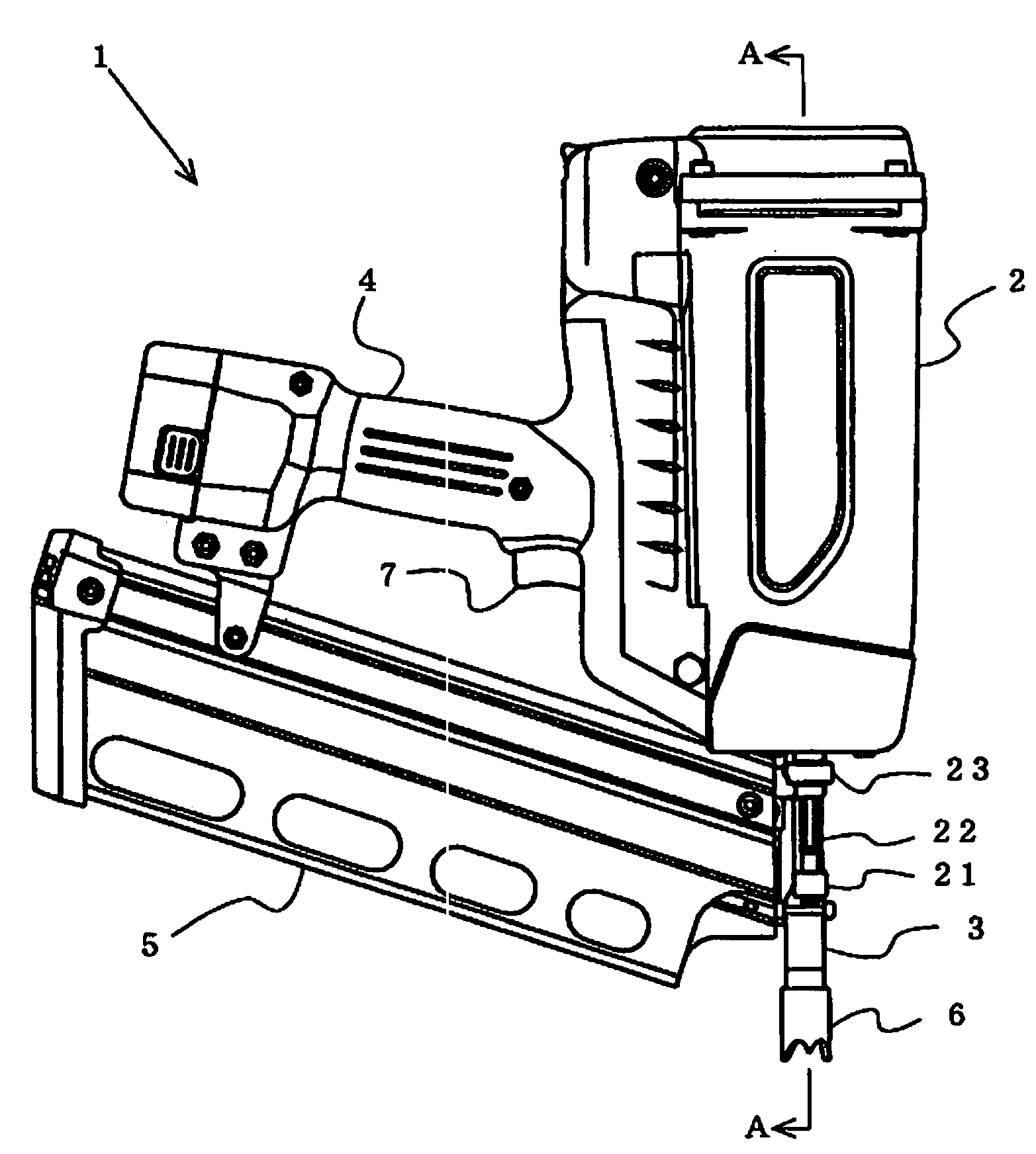
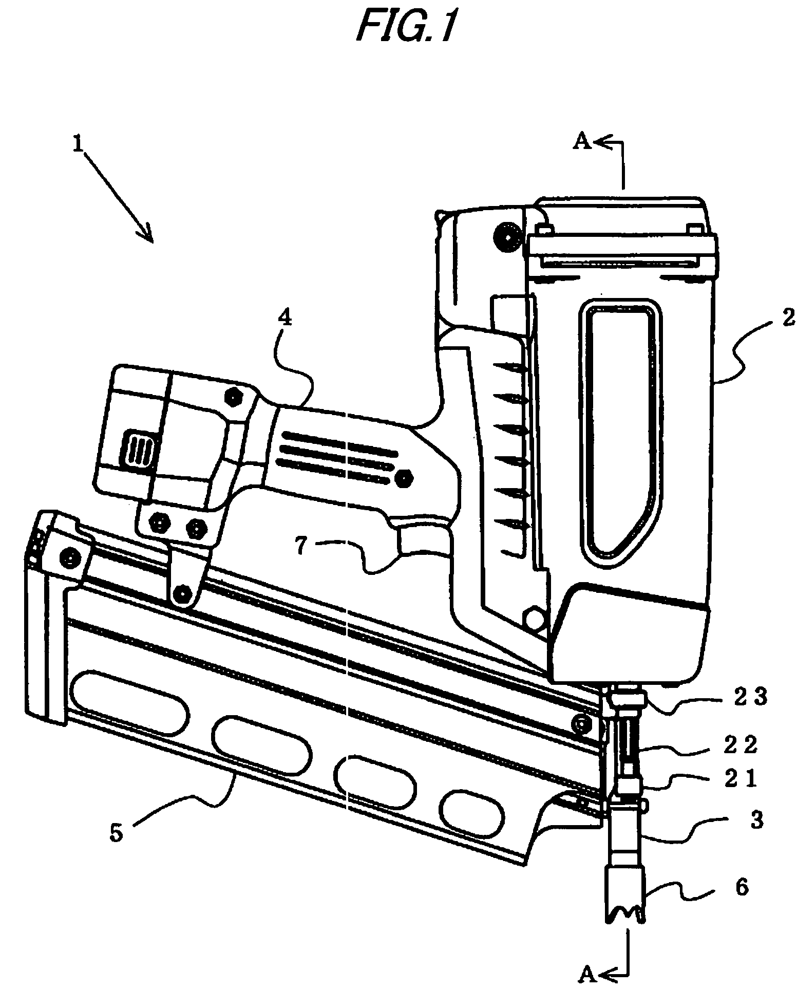
[0048]FIG. 1 shows the combustion gas drive nailing machine 1 as an example of a power drive nailing machine. The combustion gas drive nailing machine 1 is constituted by a housing 2 containing a drive mechanism, the nose portion 3 formed with an injection port for guiding a nail to a struck member and attached to a lower end portion of the housing 2, and a magazine 5 supported between a grip portion 4 formed integrally with a rear side of the housing 2 and the rear side of the nose portion 3 and containing a number of nails. Further, the combustion gas drive nailing machine 1 includes the contact member 6 arranged to project in a direction of a front end of the nose portion 3. The combustion gas drive nailing machine 1 is activated by bringing the contact member 6 into contact with a struck member to be operated to slide along the nose portion 3 and operating a trigger formed at a base portion of the grip portion 4 by the hand grabbing the grip portion 4.

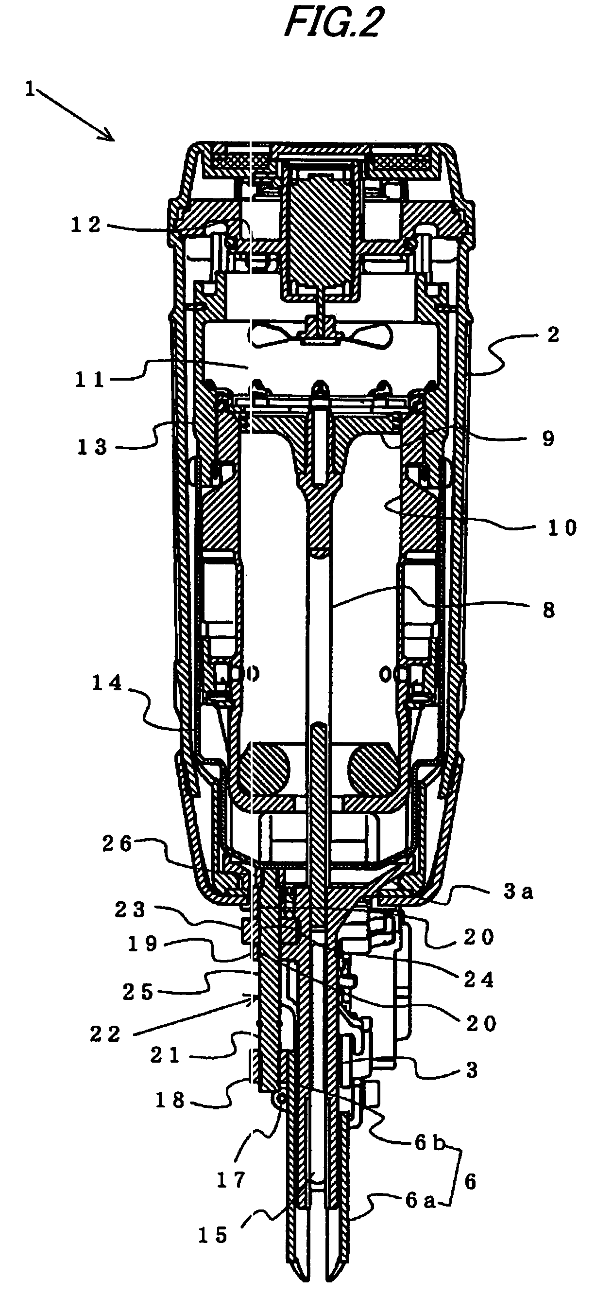
[0049]As shown by FIG. 2, i...


PUM

PropertyMeasurementUnit
lengthaaaaaaaaaa
pressureaaaaaaaaaa
depthaaaaaaaaaa

Abstract

A nailing machine includes a contact rod substantially in a straight shape and an operating dial. The contact rod is slidably and rotatably supported by a nose portion. The operating dial is slidably penetrated to be inserted by the contact rod, rotatably provided integrally with the contact rod and provided rotatably and by being restricted from being moved in an up and down direction with respect to the nose portion. A length of projecting the contact member in a direction of a front end of the nose portion is adjusted by rotating the contact rod by way of the operating dial.

Description

TECHNICAL FIELD[0001]The present invention relates to a power drive nailing machine for impulsively driving a piston contained at inside of a cylinder by a pressure of compressed air or a combustion gas or the like and striking a fastener of a nail, a pin or the like supplied to inside of an injection port to a struck member of wood, concrete or a steel plate or the like by a driver coupled to the piston.BACKGROUND ART[0002]There are a compressed air drive nailing machine for driving a piston at inside of a cylinder by introducing compressed air to inside of the cylinder containing the piston and striking a nail to a struck member of wood or the like by a driver coupled to the piston, and a combustion gas drive nailing machine formed with a combustion chamber at inside of a housing for generating a combustion gas at high pressure at inside of the combustion chamber by injecting a combustible gas to inside of the hermetically closed combustion chamber and combusting the combustible g...

Claims


Application Information

Patent Timeline
Patent Type & Authority Patents(United States)
IPC IPC(8): B25C5/02
CPCB25C1/08B25C1/008B25C7/00
Inventor OSUGA, SATOSHI
Owner MAX CO LTD
Why Eureka
Try Eureka