Radio-frequency controlled motorized roller shade

a technology of rf control and motorized roller shades, which is applied in the direction of motor/generator/converter stoppers, dynamo-electric converter control, instruments, etc., can solve the problems of increasing detection errors at rf transceivers, difficult to establish reliable rf communications between rf, and interference with rf communication, etc., to achieve the effect of increasing the signal strength of r

Active Publication Date: 2010-05-25
LUTRON TECH CO LLC
View PDF36 Cites 105 Cited by
  • Summary
  • Abstract
  • Description
  • Claims
  • Application Information

AI Technical Summary

Benefits of technology

[0011]According to a first embodiment of the present invention, a roller shade structure controlled by radio-frequency (RF) wireless communication from a control device comprises a roller tube and a conductive enclosure. The conductive enclosure is mounted inside the roller tube for enclosing a motor drive system having a motor operable to controllably rotate the roller tube in a direction at a speed when a voltage is applied to the motor. A capacitive coupling is provided between the enclosure and the roller tube, the capacitive coupling providing an increased signal strength of RF signals received by the RF receiver.
[0012]According to a second embodiment of the present invention, a roller shade structure comprises a roller for winding the shade, a circuit board, an antenna, and an electrically conductive enclosure for the motor and circuit board. The circuit board is attached to the motor and has a motor drive circuit and a filter circuit for reducing RF noise generated by the motor drive circuit and the motor. The circuit board also has an RF receiver for receiving RF control signals for controlling the motor. The antenna is coupled to the RF receiver for providing the control signals to the receiver and extends from the roller. The roller and the enclosure are electrically coupled by a low impedance at the RF frequency of the control signals.

Problems solved by technology

However, a typical roller tube is made of metal that acts as a shield which interferes with the RF communications.
Also, since the enclosure is located inside the roller tube, noise from internal sources, such as motor brushes and switching circuits (such as, for example, switching power supplies) is directed towards the RF transceiver and increases detection errors at the RF transceiver.
Accordingly, reliable RF communications are typically difficult to establish between the RF controller of the motorized roller shade and the other control devices of the RF lighting control system.

Method used


Image

  • Radio-frequency controlled motorized roller shade
  • Radio-frequency controlled motorized roller shade
  • Radio-frequency controlled motorized roller shade

Examples


Embodiment Construction

[0025]The foregoing summary, as well as the following detailed description of the preferred embodiments, is better understood when read in conjunction with the appended drawings. For the purposes of illustrating the invention, there is shown in the drawings an embodiment that is presently preferred, in which like numerals represent similar parts throughout the several views of the drawings, it being understood, however, that the invention is not limited to the specific methods and instrumentalities disclosed.

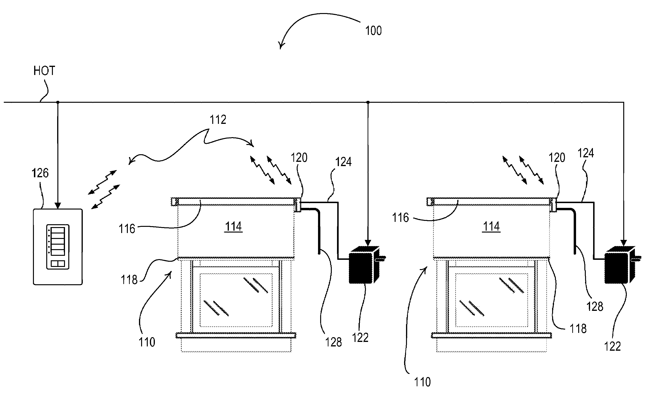
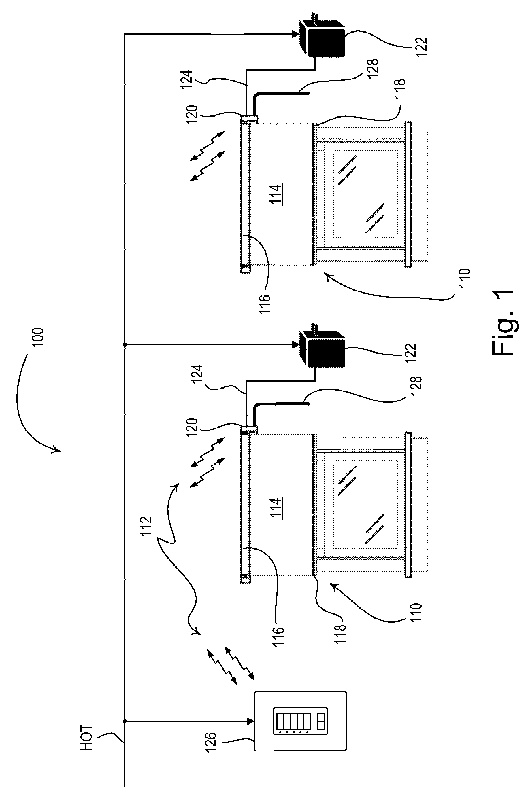
[0026]FIG. 1 is a simplified block diagram of an RF control system 100 for a plurality of motorized window treatments 110 according to the present invention. The RF lighting control system 100 includes a HOT connection to a source of AC power (not shown) for powering the motorized window treatments 110. The RF lighting control system 100 utilizes an RF communication link for communication of RF signals 112 between control devices of the system.

[0027]Each motorized window treatme...


PUM


Abstract

A roller shade structure controlled by radio-frequency (RF) wireless communication from a control device comprises a roller tube and a conductive enclosure. The conductive enclosure is mounted inside the roller tube for enclosing a motor drive system having a motor operable to controllably rotate the roller tube in a direction at a speed when a voltage is applied to the motor. A capacitive coupling is provided between the enclosure and the roller tube, the capacitive coupling providing an increased signal strength of RF signals received by the RF receiver.

Description

RELATED APPLICATION[0001]This application claims priority from commonly-assigned U.S. Provisional Patent Application Ser. No. 60 / 802,869, filed May 23, 2006, having the same title as the present invention, the entire disclosure of which is hereby incorporated by reference.BACKGROUND OF THE INVENTION[0002]1. Field of the Invention[0003]The present invention relates to radio-frequency (RF) controlled devices, and more specifically, to RF load control devices for motorized roller shades.[0004]2. Description of the Related Art[0005]Control systems for controlling electrical loads, such as lights, motorized window treatments, and fans, are known. Such control systems often use radio-frequency (RF) transmission to provide wireless communication between the control devices of the system. One example of an RF lighting control system is disclosed in commonly-assigned U.S. Pat. No. 5,905,442, issued on May 18, 1999, entitled METHOD AND APPARATUS FOR CONTROLLING AND DETERMINING THE STATUS OF E...

Claims


Application Information

Patent Timeline
Patent Type & Authority Patents(United States)
IPC IPC(8): G05B5/00
CPCH02K11/022E06B9/40H02K11/0141
Inventor CARMEN, JR., LAWRENCE R.
Owner LUTRON TECH CO LLC
Why Eureka
Try Eureka