Supercharge Your Innovation With Domain-Expert AI Agents!

Image pickup apparatus and image pickup method

a technology of image pickup and image data, which is applied in the direction of cameras, television systems, instruments, etc., can solve the problems of reducing the rate at which image data can be transferred, the difficulty of defining overlapping areas of unit images picked up, and the volume of image data that has to be transferred for a series of image pickup operations becomes enormous. , to achieve the effect of reducing the mass of the rotating part, preventing the loss of an overlapping area, and modifying the position of the reading rang

Inactive Publication Date: 2010-05-25
SONY CORP
View PDF37 Cites 16 Cited by
  • Summary
  • Abstract
  • Description
  • Claims
  • Application Information

AI Technical Summary

Benefits of technology

This approach enables the production of high-quality panoramic images with reduced discontinuities and improved handling, maintaining image quality even when the image pickup direction is manually adjusted, and reduces the cost and mechanical load of the rotating components.

Problems solved by technology

Meanwhile, it is difficult to define overlapping areas of unit images picked up by a camera system at the time of designing the camera system.
This is because the volume of image data that has to be transferred for a series of image pickup operations becomes enormous when relatively large overlapping areas are defined.
Since the rate at which image data can be transferred is limited, the intervals of picking up unit images have to be increased when a large volume of image data has to be transferred.
A camera system that requires a long time for picking up an image of a moving object is not feasible because the quality of the panoramic whole image picked up in a long shooting period is very poor.
If, on the other hand, small overlapping areas are defined, it will not be possible to produce overlapping areas when the camera system is moved slightly incorrectly to make the attempt of acquiring a whole image a complete failure.

Method used


Image

  • Image pickup apparatus and image pickup method
  • Image pickup apparatus and image pickup method
  • Image pickup apparatus and image pickup method

Examples


Embodiment Construction

[0051]Now, the present invention will be described in greater detail by referring to the accompanying drawings that illustrate preferred embodiments of the invention.

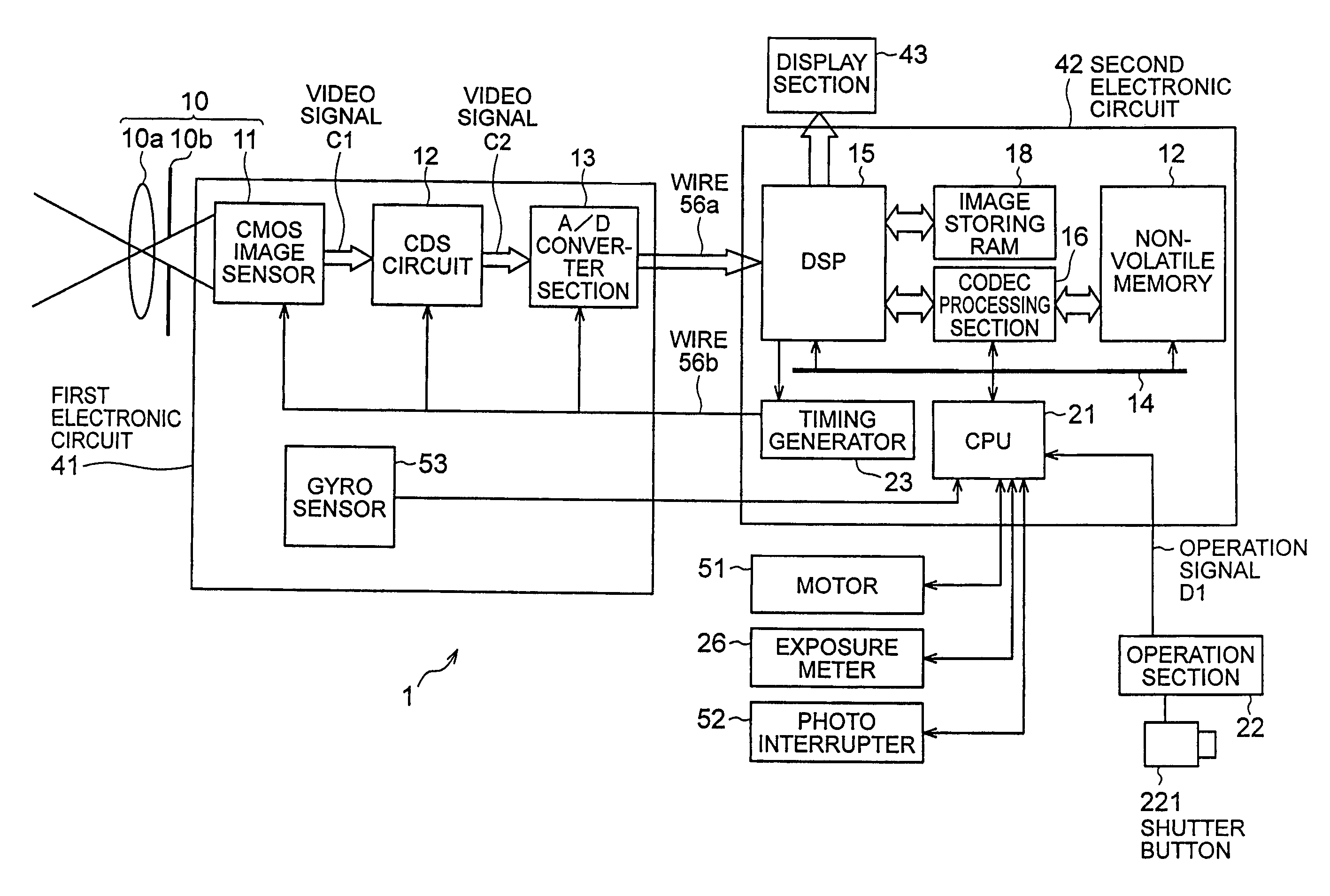
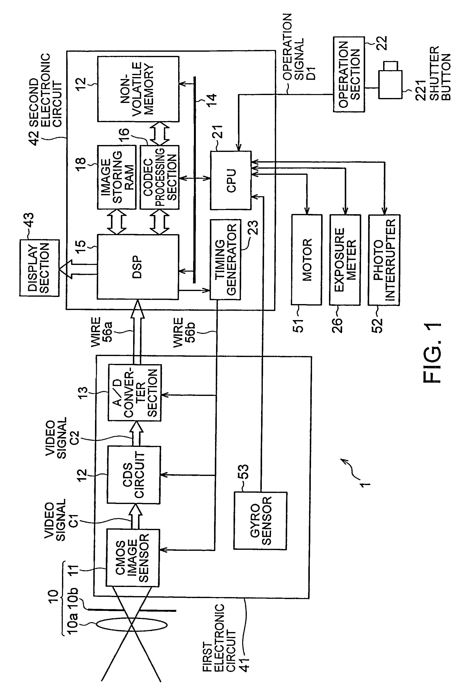
[0052]The present invention is applied to, for example, an image pickup apparatus 1 as shown in FIG. 1.

[0053]Referring to FIG. 1, the image pickup apparatus 1 comprises an image pickup section 10 for picking up an image of an object of shooting. The image pickup section 10 includes a lens 10a for focusing rays of light coming from the object to form an image of the object; a diaphragm drive section 10b for regulating the aperture of the lens by means of a shutter blade or the like for blocking the rays of light coming in from the object by way of the lens 10a and a CMOS (complementary metal-oxide semiconductor) image sensor 11 for generating an electric imaging signal C1 according to the input image of the object.

[0054]The image pickup apparatus 1 also comprises a CDS (corrected double sampling) circuit 12 for compensat...


PUM


Abstract

This invention makes it possible to produce a high quality synthesized panoramic image when it is difficult to highly precisely shift the image pickup direction. The present invention provides an image pickup apparatus for synthetically generating a first image, or a whole image of an entire object of shooting, the apparatus comprising an image pickup section that sequentially changes the image pickup direction and picks up section of images of the object of shooting to be imaged, a reading section that reads second images, each having a predetermined width and constituting a part of the image picked up on an imaging plane in the image pickup section, a defining section that defines a reading range of each second image to be read by the reading section, a relative position identifying section that identifies the relative position of each second image relative to the first image, and a synthesizing section that generates the first image by sequentially and synthetically combining the second images read out by the reading section, the defining section being adapted to determine the first quantity of movement of each second image by referring to the relative position thereof as identified by the relative position identifying section and define the reading range of the second image to be read out next according to the first quantity of movement.

Description

CROSS-REFERENCE TO RELATED APPLICATIONS[0001]The present invention contains subject matter related to Japanese Patent Application JP 2004-149679 filed in the Japanese Patent Office on May 19, 2004, the entire contents of which being incorporated herein by reference.BACKGROUND OF THE INVENTION[0002]1. Field of the Invention[0003]This invention relates to an image pickup apparatus, an image pickup method and an image pickup program for generating a whole panoramic image by gradually and sequentially shifting the image pickup direction and pasting a plurality of picked up images side by side as well as to a recording medium adapted to store such images.[0004]2. Description of the Related Art[0005]Electronic still cameras have been and being popularly used. They are designed to convert the rays of light that pass through the lens of the camera as the camera shoots the object to be imaged by means of a solid state imaging element such as CCD into video signals, record the video signals o...

Claims


Application Information

Patent Timeline
Patent Type & Authority Patents(United States)
IPC IPC(8): H04N5/225H04N5/262H04N7/00G03B15/00G03B17/56G03B37/00H04N23/40H04N101/00
CPCH04N5/232H04N5/2624H04N5/23238H04N23/531H04N23/698H04N23/63
Inventor SHIOYA, HIROYUKIOHKI, MITSUHARU
Owner SONY CORP
Features
  • R&D
  • Intellectual Property
  • Life Sciences
  • Materials
  • Tech Scout
  • Unparalleled Data Quality
  • Higher Quality Content
  • 60% Fewer Hallucinations
Learn More