Display drive device and display device

a drive device and display device technology, applied in static indicating devices, instruments, non-linear optics, etc., can solve the problems of short operating life, deterioration of the amount of solute to be dissolved, and difficulty in keeping a balance between the amount of solute, so as to prevent excessive decoloration and good display quality

Inactive Publication Date: 2010-05-25
CASIO COMPUTER CO LTD
View PDF4 Cites 38 Cited by
  • Summary
  • Abstract
  • Description
  • Claims
  • Application Information

AI Technical Summary

Benefits of technology

[0010]The present invention has an advantage that a good display quality can be obtained for a long period of time by appropriately determining the end of the decoloration step and preventing generation of the excessive decoloration, in a display drive device for driving a display unit having an electrochromic element and a display device provided with the same.

Problems solved by technology

However, a method for simply supplying a predetermined amount of voltage waveform involves a problem that it is difficult to keep a balance between the amount of the solute to separate out and the amount of the solute to be dissolved, and an operating life is short.
In other words, if coloration and decoloration are repeated many times, the balance between the amount of the solute to separate out and the amount of the solute to be dissolved is deteriorated, and this easily causes a defect where a part of the colored portion does not decolor due to excessive deposition and the electrolyte may change colors due to generation of other substance (for example, an iodine) in the electrolyte because dissolution of the solute has been progressed too much.
Particularly, if time from a coloration step to a decoloration step is made longer, the decoloration may naturally occur and this easily generates excessive decoloration.
However, the value of the wire resistance and the value of the contact resistance between the circuits generally vary widely and it is not easy to make these values constant.

Method used


Image

  • Display drive device and display device
  • Display drive device and display device
  • Display drive device and display device

Examples


first embodiment

[0039]At first, a first embodiment according to the present invention will be described.

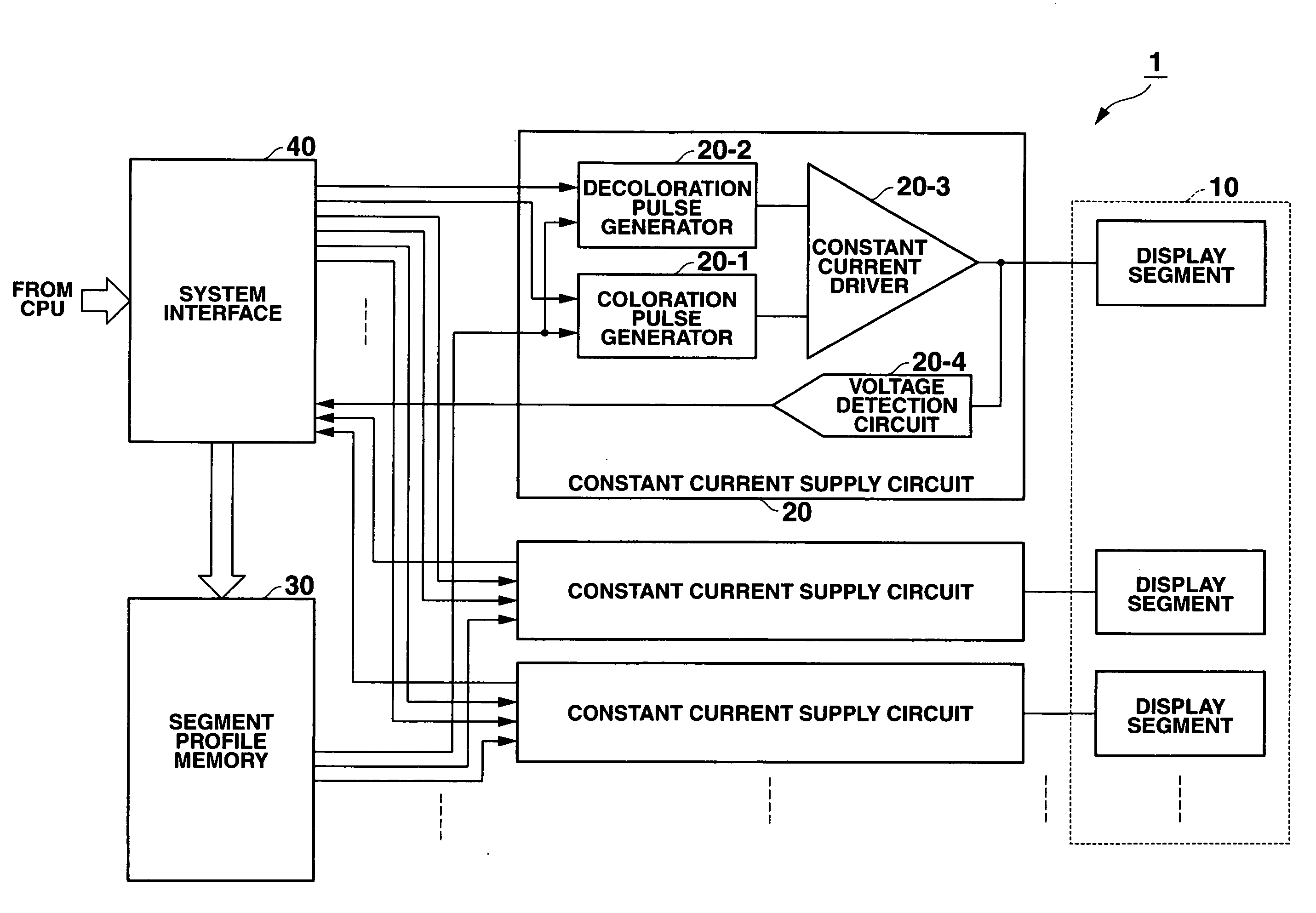
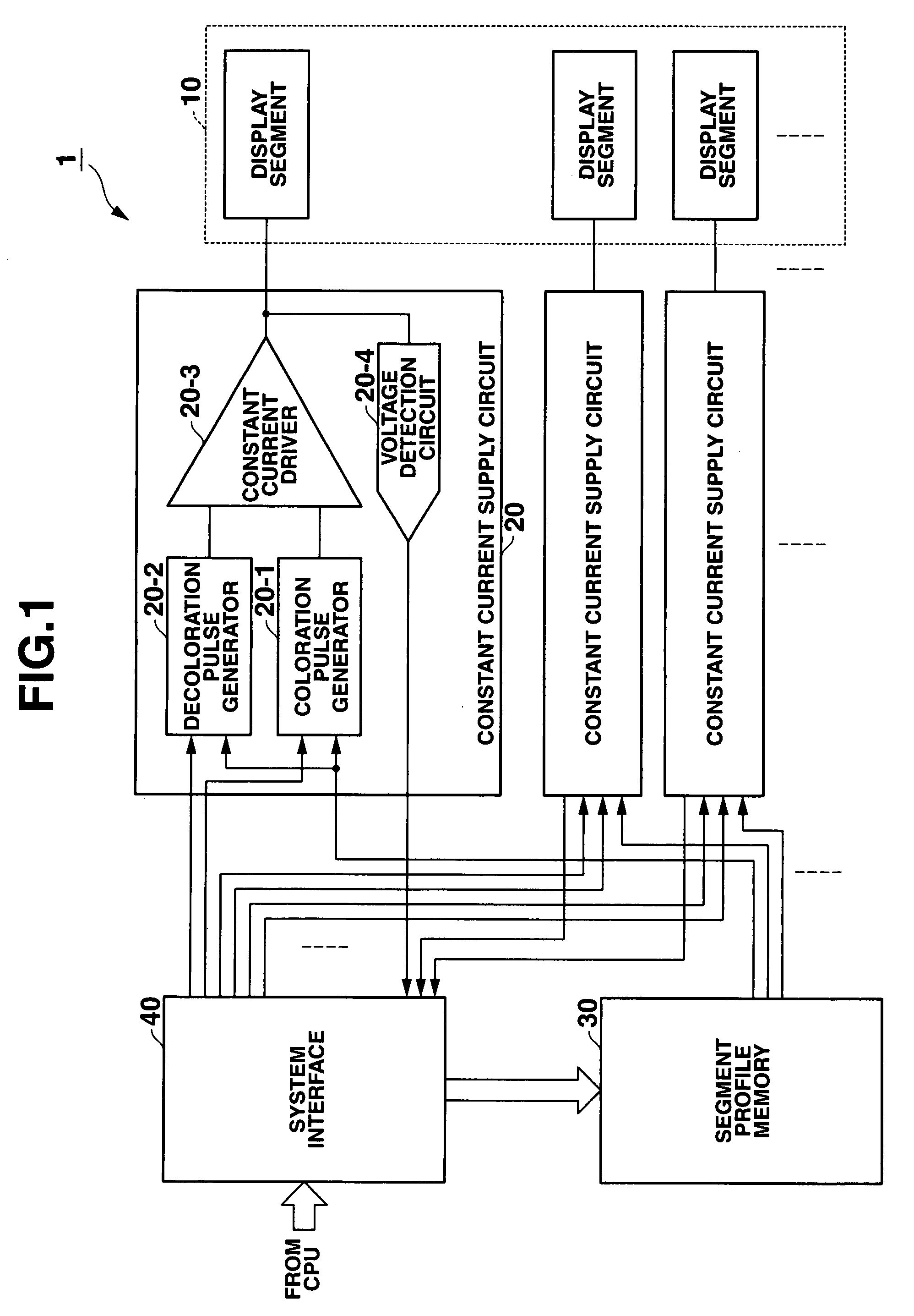
[0040]FIG. 1 is a block diagram showing a configuration of a display device, to which a display drive device according to the first embodiment of the present invention is supplied.

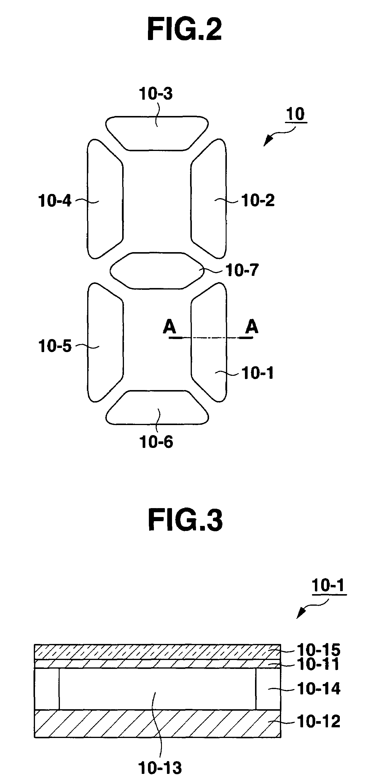
[0041]FIG. 2 is a view showing an alignment example of a display segment of a display panel.

[0042]The display device shown in FIG. 1 is formed by a display panel 10, a constant current supply circuit 20, a segment profile memory 30, and a system interface 40.

[0043]According to the display device of the present embodiment, as shown in FIG. 1, the display panel 10 has a plurality of display segments (display element) including display electrode and the display device is driven by supplying a constant current from the constant current supply circuit 20 to respective display segments. Particularly, the display device is constituted such that a value of a current to be supplied to each display segment is set to a current val...

second embodiment

[0091]Next, a second embodiment according to the present invention will be described.

[0092]Since the configuration of a display drive device according to the second embodiment is equal to that of the above-described first embodiment, the illustration and the description are herein omitted. However, according to the present embodiment, a voltage detection circuit 20-4 also detects a current flowing from the output terminal of a constant current driver 20-3 toward a positive power source +V and a voltage generated in response to a load (the resistance of the display segment, the wiring resistance or the like) which is connected to the constant current driver 20-3 when the constant current is supplied in the decoloration current pulse and then, the voltage detection circuit 20-4 inputs its voltage value in a CPU (not illustrated) via a system interface 40.

[0093]It is obvious that the voltage in response to the electromotive force generated in the display segment is detected when the de...

third embodiment

[0107]Next, a third embodiment according to the present invention will be described.

[0108]Further, since the configuration of the display drive device is equal to that of the above-described second embodiment, the illustration and the description thereof are herein omitted. However, in the present embodiment, two kinds of current values i1 and i2 are further stored in a segment profile memory 30.

[0109]FIG. 11 is a timing chart showing a change of the current and the voltage in the decoloration step by means of the display drive device according to the third embodiment.

[0110]Since the coloration step is equal to that in the above-described embodiment, the illustration and the description thereof are herein omitted.

[0111]According to the second embodiment, as shown in FIG. 10, on the part where the resistance value of the display segment is not largely changed, the constant current is continuously supplied as a decoloration current pulse, and on the part where the resistance value of ...


PUM

PropertyMeasurementUnit
timeaaaaaaaaaa
voltageaaaaaaaaaa
timeaaaaaaaaaa

Abstract

A display drive device comprises a display element being colored by injecting an electric charge into an electrolyte via an display electrode due to an oxidation-deoxidization reaction and being decolored by injecting an electric charge having an inverse polarity of the electric charge into the electrolyte, at least one constant current supply circuit which supplies a constant current as a decoloration current pulse having a predetermined pulse width to the display electrode upon the decoloration, a voltage detection circuit which detects a voltage value generated in the display electrode, and a control circuit which controls an operation of the constant current supply circuit intermittently and repeatedly supplying the decoloration current pulse from the constant current supply circuit to the display electrode upon the decoloration, and ending the decoloration on the basis of a voltage value to be detected by the voltage detection circuit.

Description

CROSS-REFERENCE TO RELATED APPLICATIONS[0001]This application is based upon and claims the benefit of priority from prior Japanese Patent Applications No. 2006-089724, filed Mar. 29, 2006; No. 2006-089725, filed Mar. 29, 2006; No. 2006-089726, filed Mar. 29, 2006; No. 2006-173948, filed Jun. 23, 2006; No. 2006-173949, filed Jun. 23, 2006; and No. 2006-173950, filed Jun. 23, 2006, the entire contents of all of which are incorporated herein by reference.BACKGROUND OF THE INVENTION[0002]1. Field of the Invention[0003]The present invention relates to a display drive device for driving a display unit having an electrochromic element and a display device provided with the same.[0004]2. Description of the Related Art[0005]There have been proposed various display devices having a display unit provided with a display element (namely, an electrochromic element) using a phenomenon such that a solute in an electrolyte separates out or dissolve due to an oxidation-deoxidization reaction by injec...

Claims


Application Information

Patent Timeline
Patent Type & Authority Patents(United States)
IPC IPC(8): G02F1/03
CPCG09G3/19G02F1/1523G09G3/2014G02F1/163G09G3/04G09G2310/0256G09G2310/06G09G2320/0242
Inventor YAMAGUCHI, TOMOHARU
Owner CASIO COMPUTER CO LTD
Why Eureka
Try Eureka