Method and apparatus for driving semiconductor lasers, and method and apparatus for deriving drive current patterns for semiconductor lasers

a laser and semiconductor technology, applied in the direction of lasers, semiconductor lasers, solid-state devices, etc., can solve the problems of laser apparatuses, laser equipment, and laser equipment, and achieve stable high-output laser beams, low cost, and efficient generation of drive current patterns

Active Publication Date: 2010-05-25
ADTEC ENG
View PDF15 Cites 4 Cited by
  • Summary
  • Abstract
  • Description
  • Claims
  • Application Information

AI Technical Summary

Benefits of technology

[0070]The method for driving semiconductor lasers according to the present invention comprises the steps of: generating a pattern of drive current values for at least one semiconductor laser, which is defined according to the amount of time which has passed since initiating driving thereof, that enables obtainment of substantially the same light output as a target light output by the automatic current control or the automatic power control; and varying the drive current of the semiconductor laser in stepwise increments according to the pattern for a predetermined period of time from initiation of drive thereof. Therefore, the light output changes in a stepwise manner, as illustrated in FIG. 18, for example. When compared against the light output of a conventional method as illustrated in FIG. 17, the constant target light output is approached in a shorter amount of time, and the range of fluctuation ΔP2 of the light output is smaller than the range of fluctuation ΔP1 of the conventional method.
[0085]As described in detail above, the method for driving semiconductor lasers of the present invention enables obtainment of stable high output laser beams simply, at low cost, and without a long startup time. Accordingly, the exposure apparatus of the present invention, which employs the driving apparatus that executes this method, has a short standby time until the output of laser beams stabilizes, which shortens the takt time of image exposure. Therefore, the semiconductor lasers, which are the exposure light sources of the exposure apparatus, can be replaced less frequently, thereby reducing the running costs of the exposure apparatus as well.

Problems solved by technology

Therefore, it is recognized that the ACC drive method, in which drive current is controlled to be constant, has a drawback that the light output changes after the laser is turned on.
This defect occurs particularly conspicuously in high output semiconductor lasers.
Similarly, this defect occurs conspicuously in laser apparatuses, in which pluralities of semiconductor lasers are mounted.
Further, blue-violet GaN type semiconductor lasers have poorer luminous efficiency and generate a greater amount of heat than red lasers.
In the APC drive method, however, a portion of the emitted light is utilized as an input to the feedback loop, causing a drawback that the amount of light to be utilized for the intended purpose is reduced.
In addition, additional costs become necessary to provide a light amount feedback loop circuit.
This generates loss in production time, thereby increasing the takt time of the laser exposure apparatuses.
The increase in the takt time deteriorates the productivity of exposure processes.
Therefore, the effective life of the semiconductor lasers is reduced by the amount of time that they are in the ON state and are not being utilized to perform exposure processes.

Method used


Image

  • Method and apparatus for driving semiconductor lasers, and method and apparatus for deriving drive current patterns for semiconductor lasers
  • Method and apparatus for driving semiconductor lasers, and method and apparatus for deriving drive current patterns for semiconductor lasers
  • Method and apparatus for driving semiconductor lasers, and method and apparatus for deriving drive current patterns for semiconductor lasers

Examples


Embodiment Construction

[0114]Hereinafter, preferred embodiments of the present invention will be described in detail with reference to the attached drawings. First, an image exposure apparatus according to a first embodiment of the present invention will be described.

[0115][Configuration of the Image Exposure Apparatus]

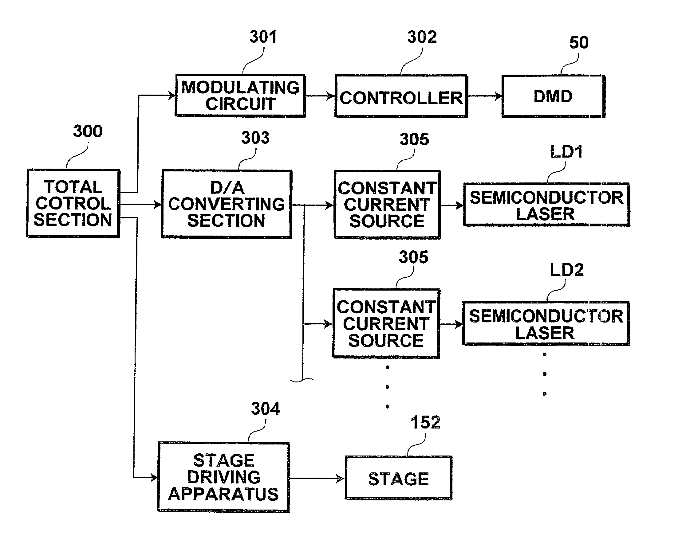
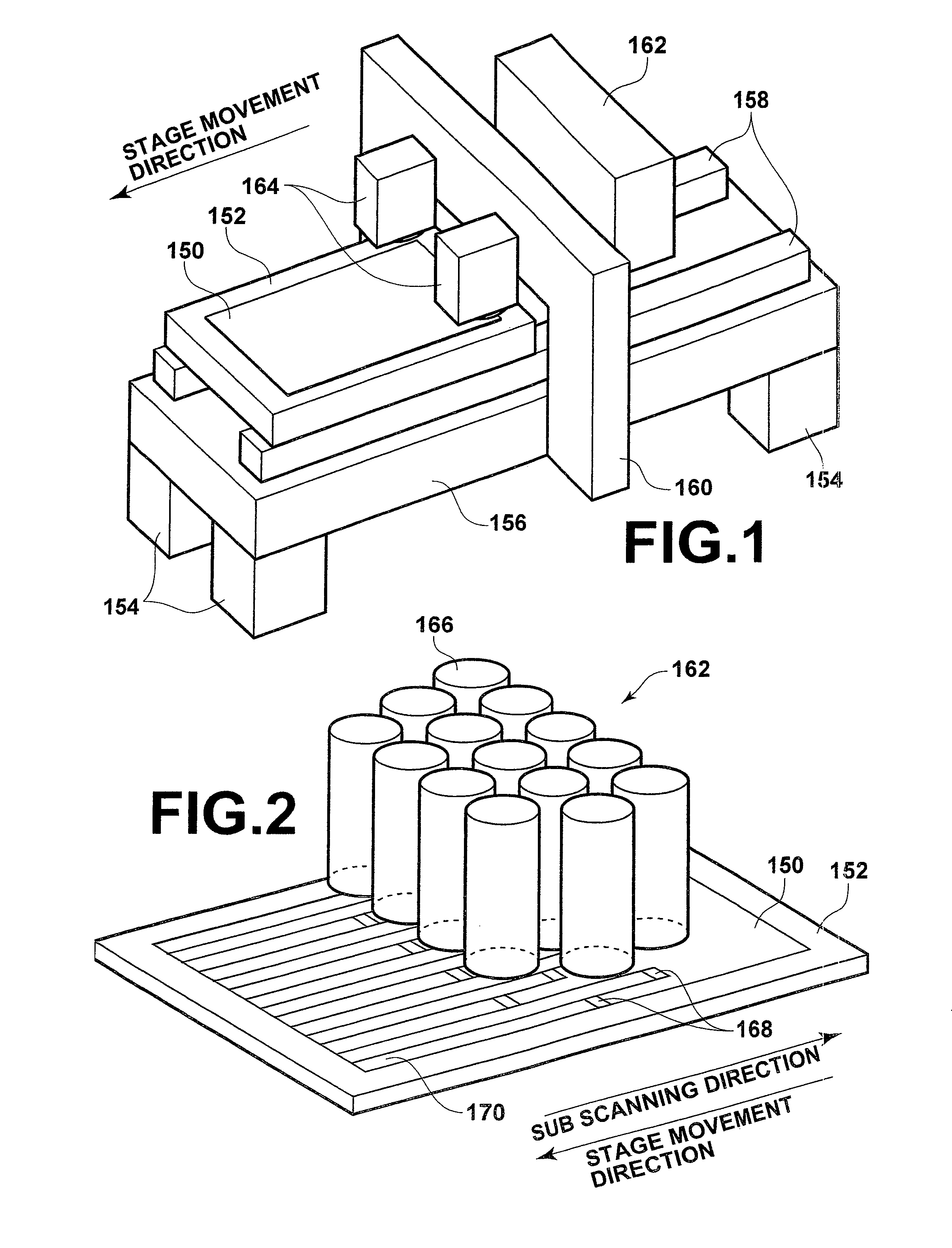
[0116]As illustrated in FIG. 1, the image exposure apparatus is equipped with a planar moving stage 152, for holding sheets of photosensitive material 150 thereon by suction. Amounting base 156 is supported by four legs 154. Two guides 158 that extend along the stage movement direction are provided on the upper surface of the mounting base 156. The stage 152 is provided such that its longitudinal direction is aligned with the stage movement direction, and supported by the guides 158 so as to be movable reciprocally thereon. Note that the image exposure apparatus is also equipped with a stage driving apparatus 304 (refer to FIG. 15), as a sub scanning means for driving the stage 152 along th...


PUM


Abstract

Semiconductor lasers are driven such that high output laser beams are stably obtained without a long start up time. A method for driving semiconductor lasers by automatic current control or automatic power control with a constant current source involves the steps of: generating a pattern of drive current values for the semiconductor lasers, which is defined according to the amount of time which has elapsed since initiating driving thereof, that enables obtainment of substantially the same light output as a target light output by the automatic current control or the automatic power control; and varying the drive current of the semiconductor lasers in stepwise increments according to the pattern for a predetermined period of time from initiation of drive thereof. A single pattern is used in common to drive the plurality of semiconductor lasers.

Description

TECHNICAL FIELD[0001]The present invention relates to a method and apparatus for driving semiconductor lasers.[0002]The present invention also relates to a method for generating a drive current pattern, which is utilized in the method for driving semiconductor lasers.[0003]Further, the present invention relates to an exposure apparatus for exposing photosensitive materials with light, which is emitted from semiconductor lasers and modulated by spatial light modulating elements.BACKGROUND ART[0004]Semiconductor lasers are in practical use in many fields. Japanese Unexamined Patent Publication No. 2005-055881 discloses a laser exposure apparatus that modulates light emitted from semiconductor lasers with spatial light modulating elements, and exposes photosensitive materials with the modulated light.[0005]In addition, GaN type semiconductor lasers that emit laser beams having wavelengths in the vicinity of 400 nm are known, as disclosed, for example, in Japanese Unexamined Patent Publ...

Claims


Application Information

Patent Timeline
Patent Type & Authority Patents(United States)
IPC IPC(8): H01S3/13H01S3/00
CPCH01S5/32341H01S5/02248H01S5/02284H01S5/0617H01S5/06808H01S5/4075H01S5/4012H01S5/4031H01S5/0683H01L2224/48091H01S5/02325H01S5/02251H01L2924/00014H01S5/068
Inventor TERAMURA, YUICHI
Owner ADTEC ENG
Why Eureka
Try Eureka