Methods and mechanisms for inserting metal fill data

a technology of metal filling and data, applied in the field of methods and mechanisms for inserting metal fill data, can solve the problems of inaccurate calculations, affecting electrical operation, unreliable conclusions, etc., and achieve the effect of extracting capacitan

Active Publication Date: 2010-05-25
CADENCE DESIGN SYST INC
View PDF31 Cites 92 Cited by
  • Summary
  • Abstract
  • Description
  • Claims
  • Application Information

AI Technical Summary

Benefits of technology

[0009]Therefore, the present approach can extract capacitance between conductors that accounts for metal fill without encumbering the designer to include it in the layout or in simulations. Prior approaches could overload an extraction system, making it impossible to get all the capacitors or otherwise, to use them effectively in simulations.BRIEF DESCRIPTION OF THE DRAWINGS

Problems solved by technology

Therefore, the purpose of metal fill is mechanical, but since it is a conductor, it can also affect the electrical operation, in particular the capacitance between connecting conductors.
It is desirable to be able to determine the set of capacitors resulting from the metal fill since ignoring the effects of metal fill on capacitance could lead to inaccurate calculations and subsequently, unreliable conclusions from simulation and other analyses that verify the integrated circuit.
However, placing too much information about the metal fill in the layout record or including nodes for metal fill in subsequent simulations that use the extracted capacitors could be disadvantageous.
As there can be substantial numbers of fill pieces, extraction and simulation may not be possible within normal limits on memory and CPU time.
Prior approaches could overload an extraction system, making it impossible to get all the capacitors or otherwise, to use them effectively in simulations.

Method used


Image

  • Methods and mechanisms for inserting metal fill data
  • Methods and mechanisms for inserting metal fill data
  • Methods and mechanisms for inserting metal fill data

Examples


Embodiment Construction

[0016]Various embodiments of the present invention are described hereinafter with reference to the figures. It should be noted that the figures are not drawn to scale and that elements of similar structures or functions are represented by like reference numerals throughout the figures. It should also be noted that the figures are only intended to facilitate the description of specific embodiments of the invention. They are not intended as an exhaustive description of the invention or as a limitation on the scope of the invention. In addition, an illustrated embodiment needs not have all the aspects or advantages of the invention shown. An aspect or an advantage described in conjunction with a particular embodiment of the present invention is not necessarily limited to that embodiment and can be practiced in any other embodiments of the present invention even if not so illustrated.

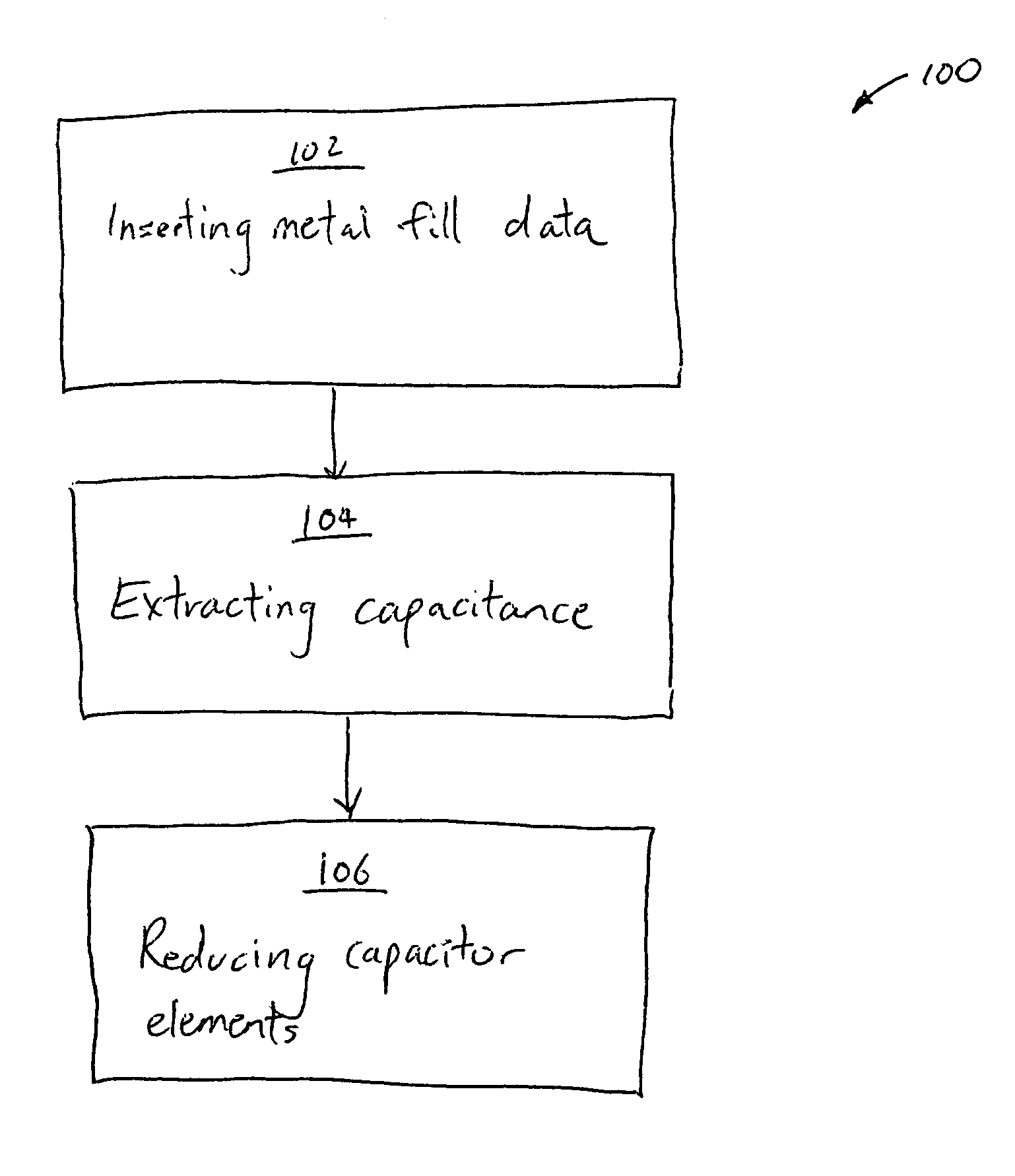
[0017]FIG. 1 illustrates a method 100 for implementing virtual metal fill (VMF) in accordance with some ...


PUM


Abstract

A method for implementing virtual metal fill includes obtaining a layout record for a circuit design, and inserting metal fill data into the layout record based on one or more rules, wherein the metal fill data represents a consolidation of actual metal fill. A method for implementing virtual metal fill includes obtaining a layout record for a circuit design, and inserting metal fill data into the layout record, the metal fill data representing a virtual metal fill having a configuration that is different from a configuration of actual metal fill.

Description

CROSS-REFERENCE TO RELATED APPLICATIONS[0001]This application claims the benefit of U.S. Provisional Patent Application Ser. No. 60 / 491,934, filed on Aug. 1, 2003, the entire disclosure of which is expressly incorporated by reference herein.BACKGROUND AND SUMMARY[0002]Computer Aided Design (CAD) for electronic systems typically involves a sequence of steps, such as layout design where devices are placed and connecting conductors are routed, layout analysis where elements representing devices and interconnect are extracted, physical verification where circuit analysis and other analyses are performed using the extracted elements, and functional verification where the design is tested against specification.[0003]Metal fill injection is a technique that is commonly used to enhance mechanical integrity and assure planarity of the deposited layers on an integrated circuit. In multi-layer ICs, metal fill is placed in sparsely populated regions. Without the support of metal fill, layers ca...

Claims


Application Information

Patent Timeline
Patent Type & Authority Patents(United States)
IPC IPC(8): G06F17/50G06F9/45G06F9/455
CPCG06F17/5081H05K3/0005G06F2217/12Y02P90/265H05K2201/09781G06F30/398G06F2119/18Y02P90/02
Inventor LENAHAN, TERRENCE A.CHIANG, KUANG-WEIWANG, JUE
Owner CADENCE DESIGN SYST INC
Why Eureka
Try Eureka