RF connector having contact terminal set with movable bridge

a technology of rf connector and contact terminal, which is applied in the direction of coupling device connection, two-part coupling device, electrical apparatus, etc., can solve the problems of misconnection between the rf connector and the rf connector is mentioned above. to prevent the misconnection

Inactive Publication Date: 2010-06-01
HON HAI PRECISION IND CO LTD
View PDF3 Cites 13 Cited by
  • Summary
  • Abstract
  • Description
  • Claims
  • Application Information

AI Technical Summary

Benefits of technology

[0007]An object, therefore, of the invention is to provide a new and improved RF connector of the character described able to provide a planar surface contact, thereby preventing the misconnection between the RF connector and the mating coaxial connector.

Problems solved by technology

Unfortunately, problems are encountered with the RF connectors mentioned above.
This kind of structure always leads to a misconnection between the mating coaxial connector and the RF connector due to providing a point contact therebetween.

Method used


Image

  • RF connector having contact terminal set with movable bridge
  • RF connector having contact terminal set with movable bridge
  • RF connector having contact terminal set with movable bridge

Examples


Embodiment Construction

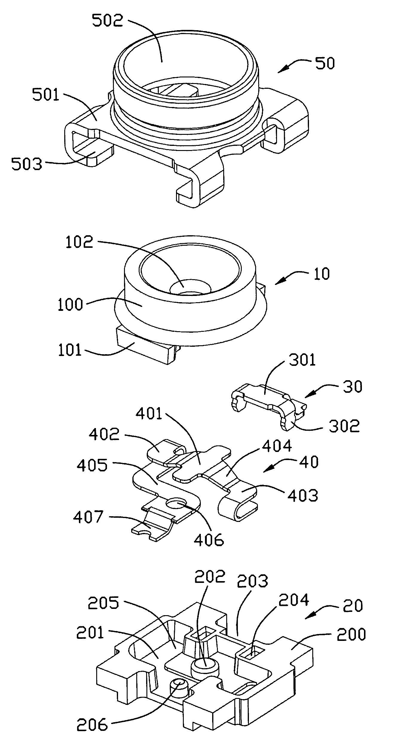
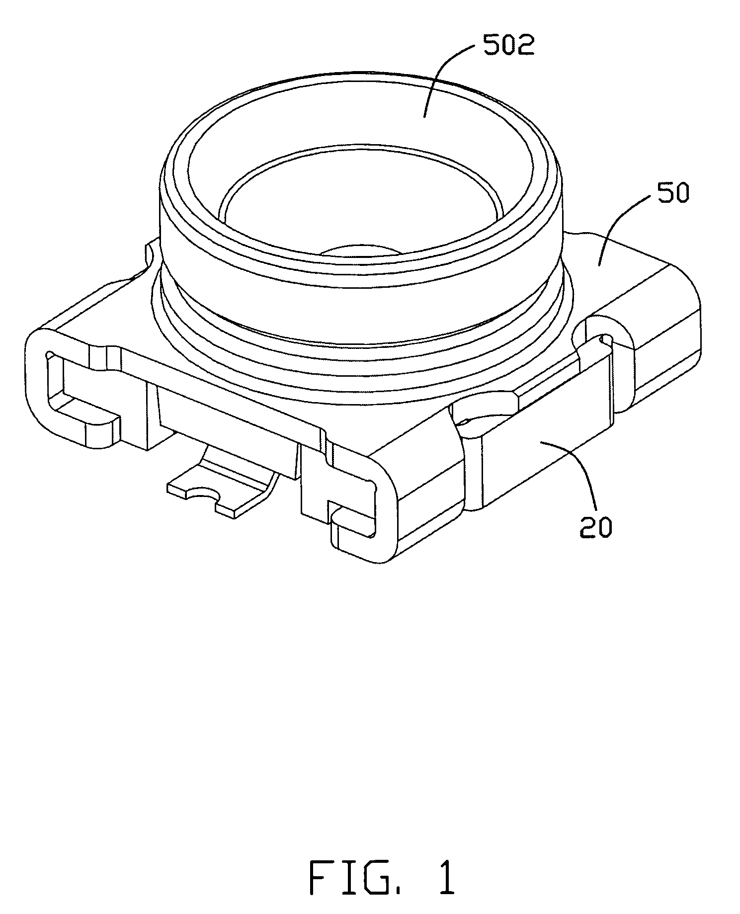
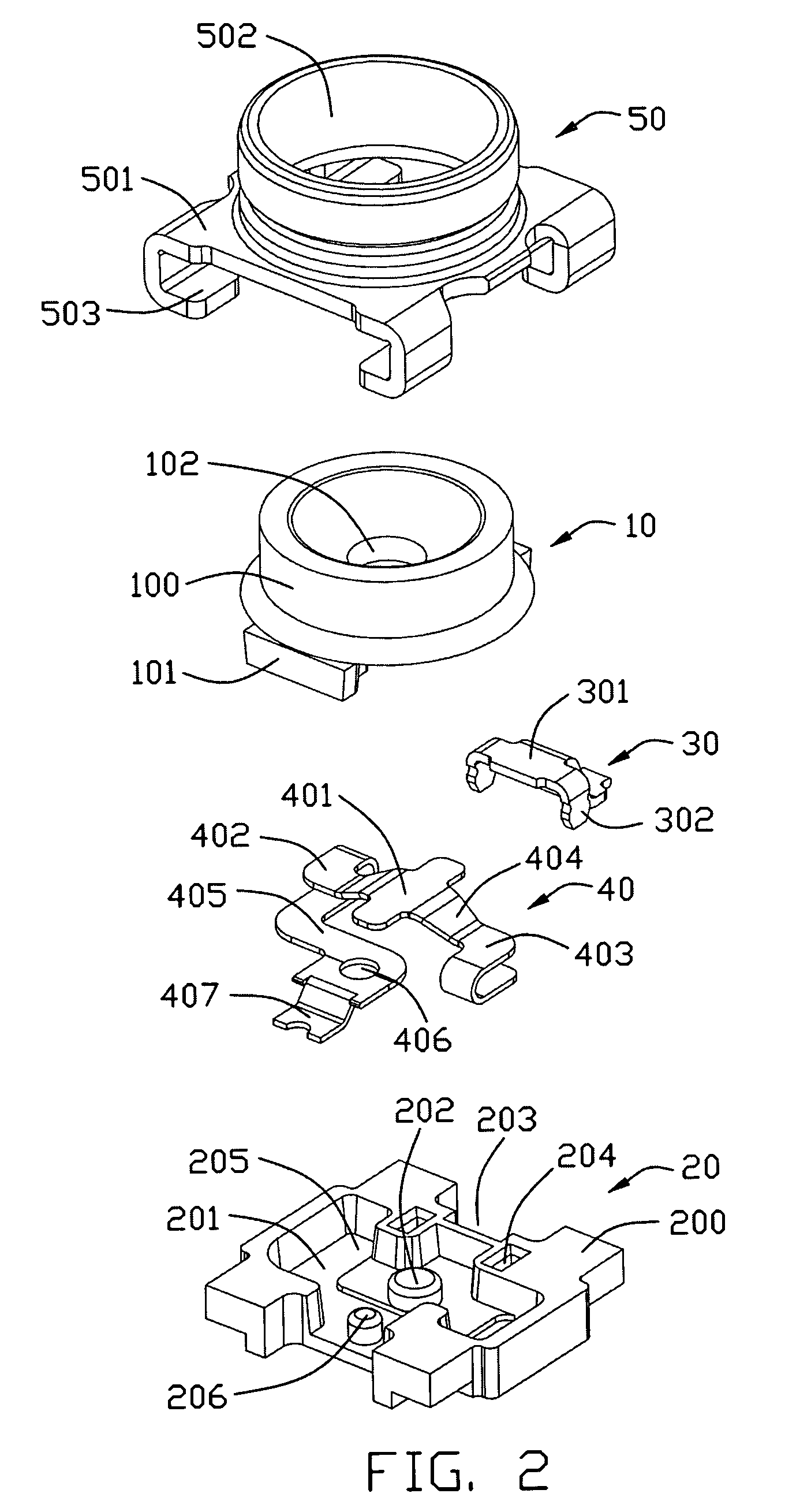
[0015]Referring to FIGS. 1-4, a RF connector for receipt of a central contact of a mating coaxial connector to be inserted therein, comprises an insulative case including an upper insulative case portion 10 and a lower insulative case portion 20, the lower insulative case portion 10 defining a space section 201 thereof; an upper fixed contact 30; a lower movable contact 40, the lower movable contact 40 essentially stacked in a vertical direction and received in the space section 201; and a metal shell 50 shielding the insulative case.

[0016]Referring to FIGS. 2-3, the upper insulative case portion 10 includes a mating section 100 with a pair of retention blocks 101 defined on a bottom surface 103 symmetrically. A pin hole 102 for receiving a contact of a mating coaxial connector runs through the upper insulative case portion 10 along a direction which is perpendicular to the bottom surface 103.

[0017]The lower insulative case portion 20 includes a base section 200 having a space secti...


PUM


Abstract

A RF connector comprising: an insulative housing defining a space section; an upper fixed contact and a lower movable contact are disposed on two opposite sides of the housing in a first direction, each of said upper fixed contact and said lower movable contact including a contact section in the space section and a solder tail exposed outside of the housing, the lower movable contact having on two opposite sides a pair of bending ends disposed which is a lying U-shape; and an upper case mounted upon the housing and defining a plug insertion passageway; and a metallic shell enclosing said upper case and the housing.

Description

BACKGROUND OF THE INVENTION[0001]1. Field of the Invention[0002]The present invention relates to a RF connector, and more particularly, to a RF connector having contact terminal set with a moveable bridge selectively disconnecting an upper and a lower parts.[0003]2. Background of the Invention[0004]RF connectors are known to set up an electrical connection between an electronic component and a printed circuit board. U.S. Pat. No. 6,554,630 issued to Murata on Apr. 29, 2003 discloses a type of connector mounted to a printed circuit board. The connector comprises a frame, a movable spring portion having two ends that are supported by the frame and a central portion thereof that is movable and is elastic; a contact portion that is integral with the movable spring portion and that is arranged to come into contact with and connect to a fixed terminal; a fixed portion that is integral with the frame and is arranged to be sandwiched by an upper insulating case portion and a lower insulatin...

Claims


Application Information

Patent Timeline
Patent Type & Authority Patents(United States)
IPC IPC(8): H01R29/00H01R24/38
CPCH01R13/7033H01R24/50H01R24/46H01R12/57H01R2103/00Y10S439/944
Inventor WANG, LELANDHSIAO, SHIH-CHIDU, JIN-LIANGZHOU, JUNWU, ZHENG-WANGRU, SHUO-BIN
Owner HON HAI PRECISION IND CO LTD
Why Eureka
Try Eureka