Connectors and cables for use with ventricle assist systems

a technology of assist system and connecting cable, which is applied in the field of connecting and connecting cables for use with ventricle assist system, can solve the problems of affecting the normal functioning of the heart, affecting the function of the heart, and affecting the ability of the heart to pump enough blood to the body, so as to prevent water or dust ingress

Active Publication Date: 2018-09-13
TC1 LLC
View PDF0 Cites 9 Cited by
  • Summary
  • Abstract
  • Description
  • Claims
  • Application Information

AI Technical Summary

Benefits of technology

[0006]Embodiments described herein include connector assemblies for coupling externally worn components of medical systems including implanted or worn medical devices. The connector assemblies can include connector cables having a flat cross section, conductors for transferring electrical power, and / or an optical fiber for transmitting data. Connector cables having a flat cross section conform well with the body of a patient, thereby being more comfortable and inhibiting twisting of the connector cable. The conductors and the optical fiber can be arranged in a symmetrical linear array, thereby preventing misconnection via improper orientation. The connector assemblies can include sealed contacts that are easily cleaned without penetration of cleaning fluid into components of the medical system. A connector assembly can include a latching mechanism configured for secure connection of the connector assembly to a component of the medical system. One embodiment of the invention is directed to forming a system using any of the devices described herein.
[0011]In many embodiments of the assembly, the electrical conductors and the optical fiber are arranged to allow increased flexibility. In some embodiments, the electrical conductors and the optical fiber are arranged in a linear array within the connector cable so that the connector cable has an elongated rectangular cross section. In some embodiments, the electrical conductors include two redundant pairs of conductors arranged symmetrically on opposite sides of the optical fiber to enable coupling of the output connector to the input connector in each of two opposite orientations.
[0015]In many embodiments of the system, the electrical conductors and optical fiber may be arranged to allow for flexibility. In some embodiments, the electrical conductors and the optical fiber are arranged in a linear array within the connector cable so that the connector cable has an elongated rectangular cross section. In some embodiments, the electrical conductors include two redundant pairs of conductors arranged symmetrically on opposite sides of the optical fiber to enable coupling of the battery module to the external controller input connector in each of two opposite orientations.
[0023]In many embodiments of the battery module, the electrical conductors and optical fiber may be arranged for increased flexibility. In some embodiments of the battery module, the electrical conductors and the optical fiber are arranged in a linear array within the connector cable so that the connector cable has an elongated rectangular cross section. In some embodiments of the battery module, the electrical conductors include two redundant pairs of conductors arranged symmetrically on opposite sides of the optical fiber to enable coupling of the battery module output connector to the medical device input connector in each of two opposite orientations. In many embodiments, the battery module may include a spooling assembly on which the connector cable can be spooled and unspooled to vary a length by which the connector cable extends from the housing.
[0028]In many embodiments of the system, the electrical conductors and optical fiber may be arranged to allow for flexibility. In some embodiments, the electrical conductors and the optical fiber are arranged in a linear array within the connector cable so that the connector cable has an elongated rectangular cross section.
[0035]In still another aspect, a method is provided for coupling a battery module to a medical support system including an implantable or wearable medical device. The battery module may include a first housing, one or more battery cells disposed within the first housing, a connector cable fixedly connected with the first housing and extending from the first housing to a distal end of the connector cable, the connector cable including electrical conductors and an optical fiber, and a battery module output connector connected to the distal end of the connector cable. The method may include electrically connecting metal pins of the battery module output connector to metal contact plates of an input connector of the medical support system so as to allow transfer of power from the one or more battery cells to the medical support system, wherein the input connector is mounted to a second housing of the medical support system, has no moving parts, and is sealed to prevent water or dust ingression into the second housing. The method may further include optically connecting the optical fiber to an optical connection of the input connector of the medical support system so as to allow transmission of data between the battery module and the medical support system. The method may further include latching the battery module output connector to the second housing of the medical device so as to physically connect the battery module to the medical support system.

Problems solved by technology

People with heart failure often have shortness of breath and fatigue.
Years of living with blocked arteries and / or high blood pressure can leave a heart too weak to pump enough blood to the body.
As symptoms worsen, advanced heart failure develops.

Method used


Image

  • Connectors and cables for use with ventricle assist systems
  • Connectors and cables for use with ventricle assist systems
  • Connectors and cables for use with ventricle assist systems

Examples


Embodiment Construction

[0048]In the following description, various embodiments of the present invention will be described. For purposes of explanation, specific configurations and details are set forth in order to provide a thorough understanding of the embodiments. However, it will also be apparent to one skilled in the art that the present invention may be practiced without the specific details. Furthermore, well-known features may be omitted or simplified in order not to obscure the embodiment being described.

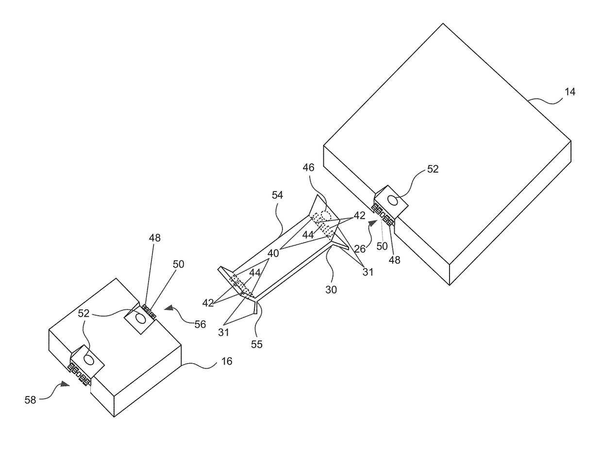
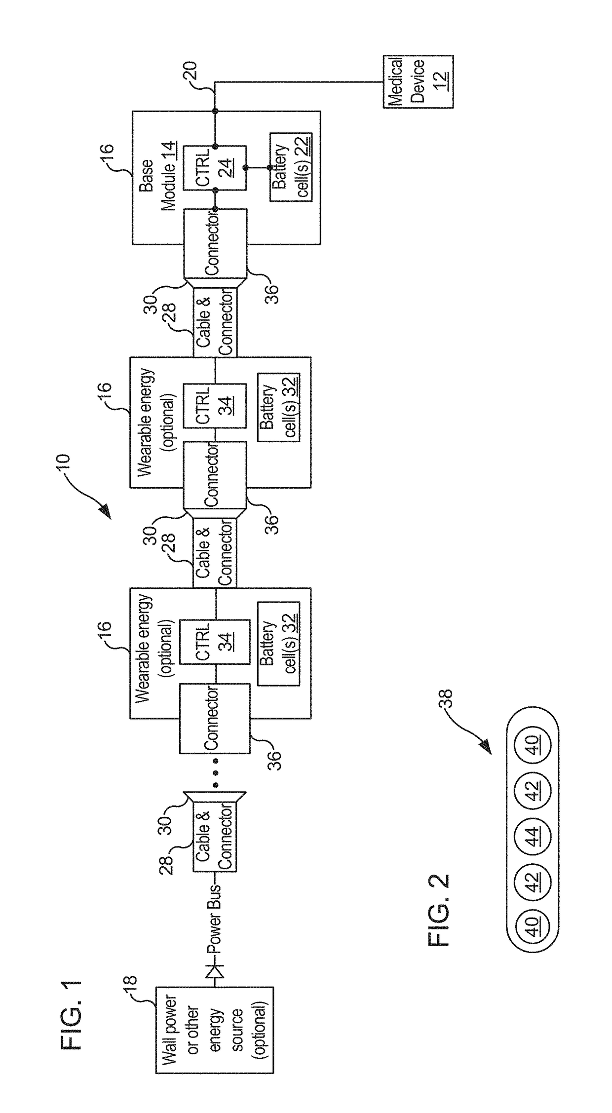
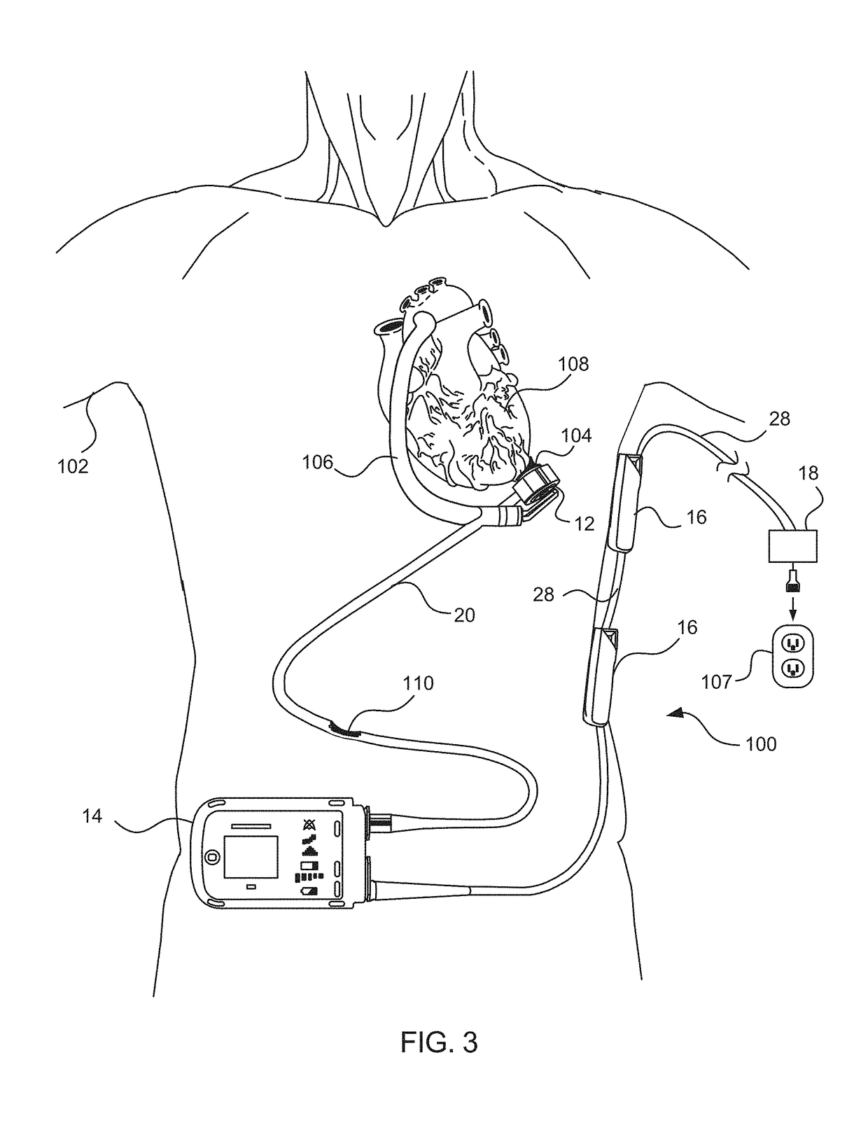
[0049]Referring now to the drawings, in which like reference numerals represent like parts throughout the several views, FIG. 1 shows a system 10, in accordance with many embodiments, for supplying power to a medical device worn by a user or implanted in the user. The system 10 includes a wearable or implantable medical device 12, a base module 14, a plurality of external battery modules 16, and a non-worn energy source 18. The external battery modules 16 are configured for selective serial connec...


PUM


Abstract

Systems, assemblies, and related modules for connecting components of medical devices employ connector cables with electrical conductors and optical fibers. A connector assembly for coupling a battery module with a medical system including an implanted or worn medical device includes an input connector and an output connector. The input connector includes metal contact plates, has no moving parts, and is sealed to prevent water or dust ingression into the housing. The output connector includes metal pins to electrically couple to the metal plates of the input connector, a connector cable including electrical conductors coupled to the metal pins configured to transmit electrical power and an optical fiber configured to transmit data, and a latching mechanism disposed at an end of the output connector configured to physically attach the output connector to the housing. The cable body has a substantially flat cross-section.

Description

CROSS-REFERENCE TO RELATED APPLICATION[0001]The present application is a continuation of PCT / US2016 / 062619 filed Nov. 17, 2016, which claims priority to and benefit of U.S. Provisional Application No. 62 / 258,292, filed Nov. 20, 2015, the disclosures of which are incorporated herein by reference in their entirety for all purposes.BACKGROUND[0002]Ventricular assist devices, known as VADs, often include an implantable blood pump and are used for both short-term (i.e., days, months) and long-term applications (i.e., years or a lifetime) when a patient's heart is incapable of providing adequate circulation, commonly referred to as heart failure or congestive heart failure. According to the American Heart Association, more than five million Americans are living with heart failure, with about 670,000 new cases diagnosed every year. People with heart failure often have shortness of breath and fatigue. Years of living with blocked arteries and / or high blood pressure can leave a heart too wea...

Claims


Application Information

Patent Timeline
Patent Type & Authority Applications(United States)
IPC IPC(8): A61M1/12A61M1/10A61M60/178A61M60/183A61M60/232A61M60/508A61M60/861A61M60/871
CPCA61M1/127A61M1/101A61M1/1008A61M1/122A61M60/871A61M60/508A61M60/232A61M60/183A61M60/178A61M60/861A61M60/148
Inventor CONYERS, KEVINROMERO, JAIME ARTURO
Owner TC1 LLC
Why Eureka
Try Eureka