Disk array system

a technology of array system and disk, which is applied in the direction of lighting and heating apparatus, electrical apparatus casing/cabinet/drawer, instruments, etc., can solve the problems of difficult to increase the power feed wiring of the backboard internal layer, disadvantage in maintenance, and difficult to closely locate the data signal wiring with the power feed wiring, etc., to achieve convenient maintenance, improve processing performance, and improve the effect of efficiency

Inactive Publication Date: 2008-01-29
HITACHI LTD
View PDF4 Cites 9 Cited by
  • Summary
  • Abstract
  • Description
  • Claims
  • Application Information

AI Technical Summary

Benefits of technology

[0009]It is difficult to closely locating the data signal wiring with the power feed wiring due to, for example, influence of power supply noise generated by the power feed wiring with respect to the data signal wiring. In other words, the data signal wiring and the power feed wiring place mounting restrictions on each other. When the data signal wiring and the power feed wiring are to be located near each other, it would be an object to prevent problems of, for example, erroneous signals by suppressing the influence of the power supply noise.
[0031]Particularly, in a disk array system which is according to a specification of downsized logical PKs, erroneous connection can be prevented and advantages in terms of maintenance are also achieved, since, for example, logical PKs which are divided into halves compared with conventional ones and according to a uniform specification can be realized, and the logical PKs can be inserted in the same direction.

Problems solved by technology

It is difficult to closely locating the data signal wiring with the power feed wiring due to, for example, influence of power supply noise generated by the power feed wiring with respect to the data signal wiring.
Also, it is difficult to increase the power feed wiring of the backboard internal layers in order to, for example, increase the supply current because of limitation on board manufacturing and cost increase.
If specification of the connection of the logical PKs cannot be made uniform in relation to downsizing of the logical PKs, it will be a disadvantage in terms of maintenance.

Method used


Image

  • Disk array system
  • Disk array system
  • Disk array system

Examples


Embodiment Construction

[0047]Hereinafter, embodiments of the present invention will be described in detail with reference to drawings. In all the drawings for explaining the embodiments, same parts are basically denoted by the same reference numerals, and repeated descriptions thereof are omitted. FIGS. 1 to 11 are drawings for explaining a disk array system of the present embodiment. FIGS. 12 and 13 are drawings for explaining a conventional disk array system for comparison with the present embodiment.

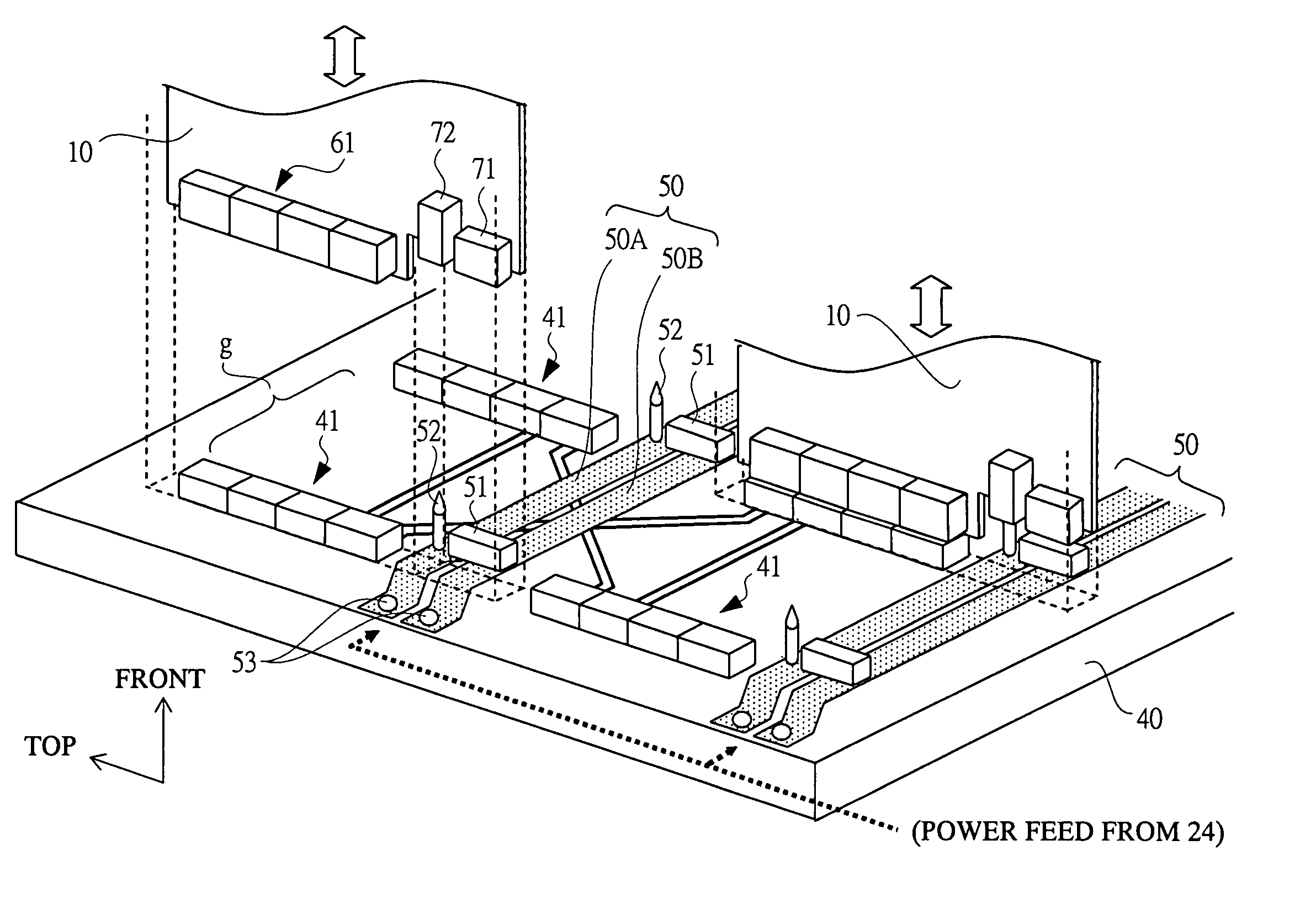
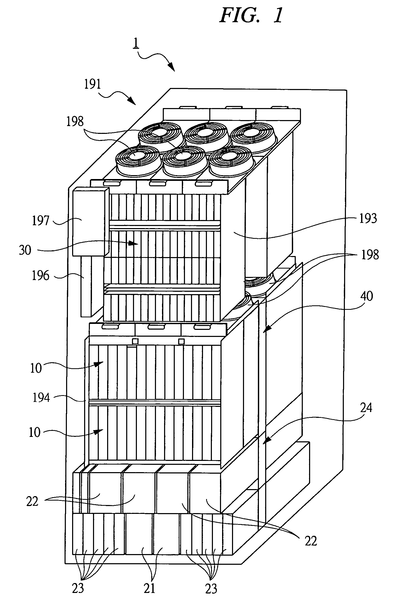
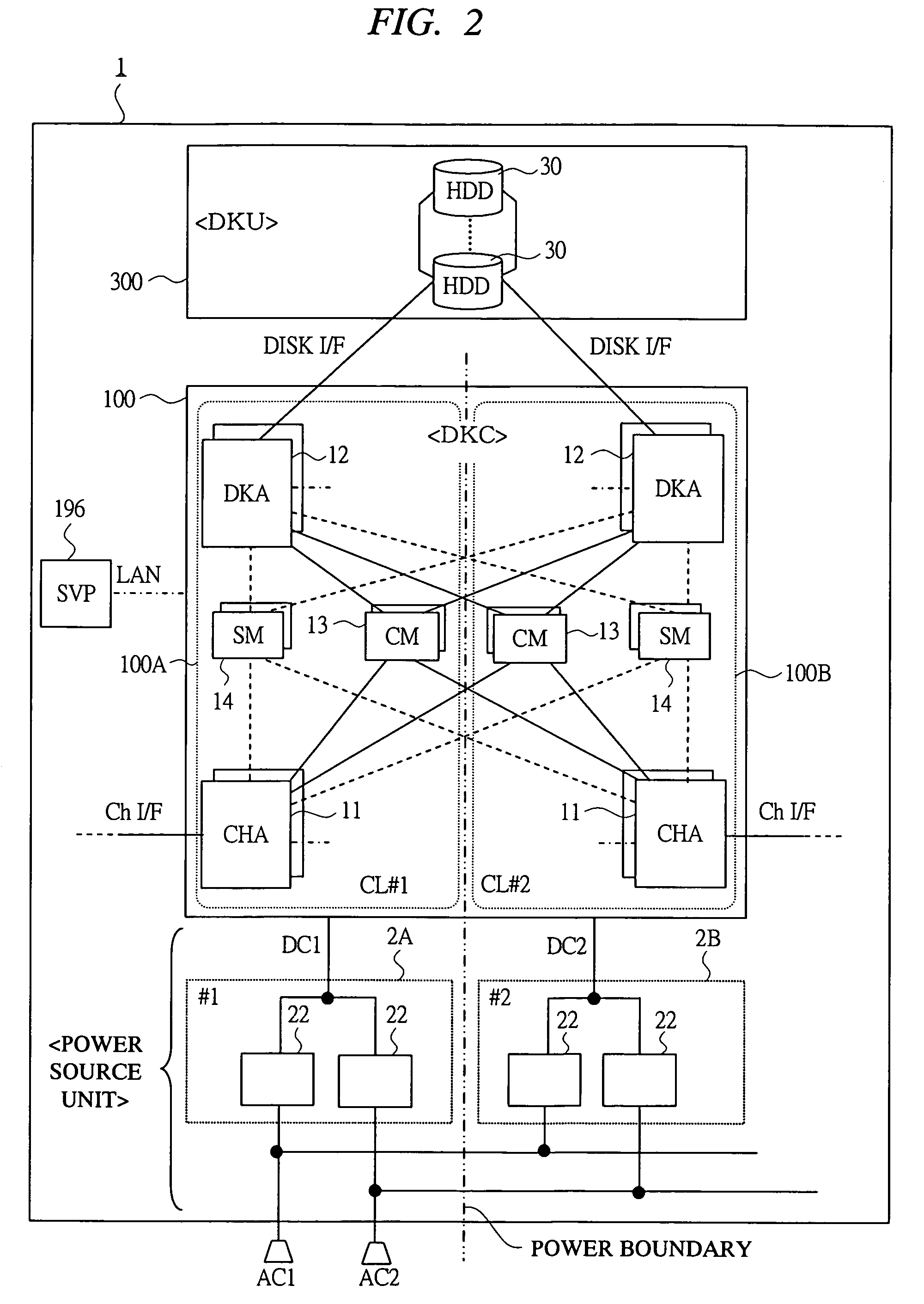
[0048]A disk array system 1 of a first embodiment of the present invention is configured such that a plurality of same-type logical PKs (10) is connected in parallel in the lateral direction on both sides of a backboard (40) in a DKC (100). The configuration is corresponding to a system in which, in the vertical direction, two logical PKs (10) which are uniformly oriented can be inserted to and removed from upper and the lower areas (“a” and “b”) of the face of the backboard (40). In this configuration, a p...


PUM


Abstract

In a disk array system, techniques advantageous in terms of economy and maintenance and capable of realizing high-density wiring of data signal wiring and power feed wiring on a backboard, and flexibly implementing specification change, processing performance improvement, etc. are provided according to a DKC mounting method different from conventional ones. In a power feed unit of the backboard, the power feed wiring comprises a bus bar of three-dimensional structure which reserves a gap distance with respect to a face of the backboard. The data signal wiring connecting connectors is provided in an area below the bus bar, thereby providing high-density wiring. The gap distance is formed to meet a design specification which makes the power supply noise influence of the power feed wiring of the bus bar on the data signal wiring satisfactory small. Power feed connectors and locator pins for logical packages are connected on the bus bar.

Description

CROSS-REFERENCE TO RELATED APPLICATION[0001]The present application claims priority from Japanese Patent Application No. JP 2005-145375 filed on May 18, 2005, the content of which is hereby incorporated by reference into this application.BACKGROUND OF THE INVENTION[0002]The present invention relates to a disk array system which is provided with storage devices such as hard disk drives (HDDs) and a storage control device for controlling storage of data with respect to the storage devices and is capable of performing RAID control. In particular, relates to techniques for mounting, for example, wiring for power feed and data signal on the boards constituting the storage control device.[0003]In a conventional disk array system, the storage control device (DKC) has a configuration in which a plurality of processing-function-installed boards (referred to as logical substrates) provided in a form of, for example, packages (referred to as PKs) is mutually connected to a backboard (also call...

Claims


Application Information

Patent Timeline
Patent Type & Authority Patents(United States)
IPC IPC(8): G06F1/16H05K7/00
CPCG11B33/126H05K7/1457G06F1/189
Inventor SUEYOSHI, JUNYA
Owner HITACHI LTD
Why Eureka
Try Eureka