System and method of fluid filtration utilizing cross-flow currents

a fluid filtration and cross-flow current technology, applied in the field of filter systems, can solve the problems of reducing the effective filtration area and relatively short usable life, and achieve the effect of prolonging the operating period of the filter unit and improving the flux rate across the filter media

Inactive Publication Date: 2010-06-01
DUAL VORTEX MICROFILTRATION
View PDF13 Cites 3 Cited by
  • Summary
  • Abstract
  • Description
  • Claims
  • Application Information

AI Technical Summary

Benefits of technology

[0007]The present invention is directed to a filter system utilizing a cross flow filtration assembly which develops secondary flow currents in a fluid flowing in a spiral flowpath about filter cartridges. Desirably the secondary flow currents developed by the spiral flowpath are Dean-Flow currents. Dean-Flow currents describe a particular flow regime developed for a spiraling fluid flowpath when fluid is forced therethrough at a critical flow velocity. FIG. 25 illustrates Dean-Flow currents established around a filter cartridge within a filter housing having spiral guides. Dean-Flow currents are developed in opposing pairs of corkscrew vortices which travel along the spiral fluid flowpath and provide a shear cleaning current across the filter media surface so as to conduct away particles entrapped by the filter media. Fluid flowing through a spiral flowpath at less than the Dean-Flow critical velocity will not develop the opposing corkscrew currents therein while fluid flowing too quickly through a spiral flowpath degenerates into a purely turbulent flow regime. Dean-Flow currents have been demonstrated to better maintain the flux rate across a filter media so as to extend the operating period of a filter unit between required backflushing or maintenance.

Problems solved by technology

This situation results in formation of a cake layer blocking openings of the filter, whereby the effective filtration area is reduced.
As a result, one significant limitation of a cartridge filter is a relatively short usable life, particularly in applications having high particle counts.

Method used


Image

  • System and method of fluid filtration utilizing cross-flow currents
  • System and method of fluid filtration utilizing cross-flow currents
  • System and method of fluid filtration utilizing cross-flow currents

Examples


embodiment 101

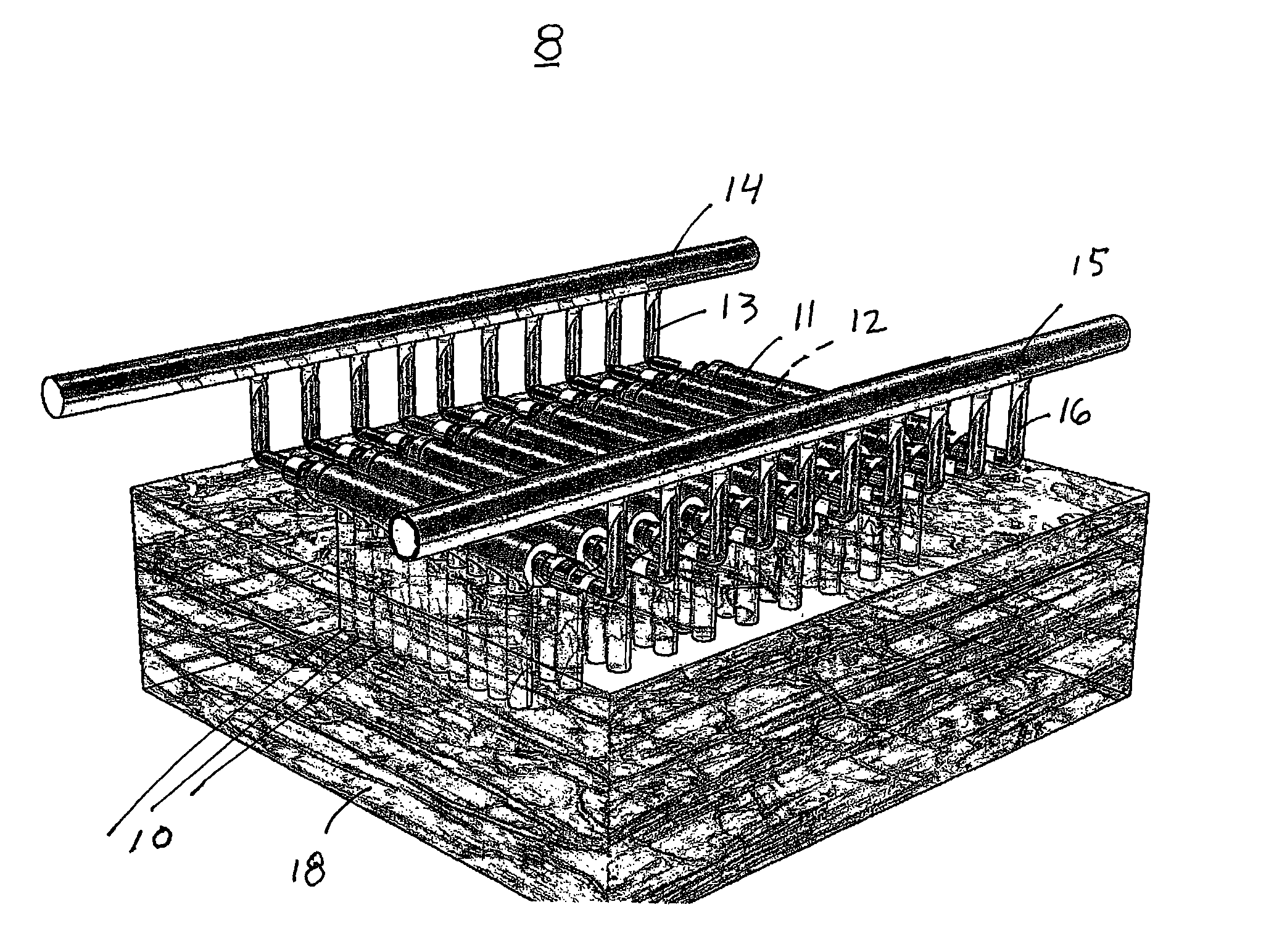
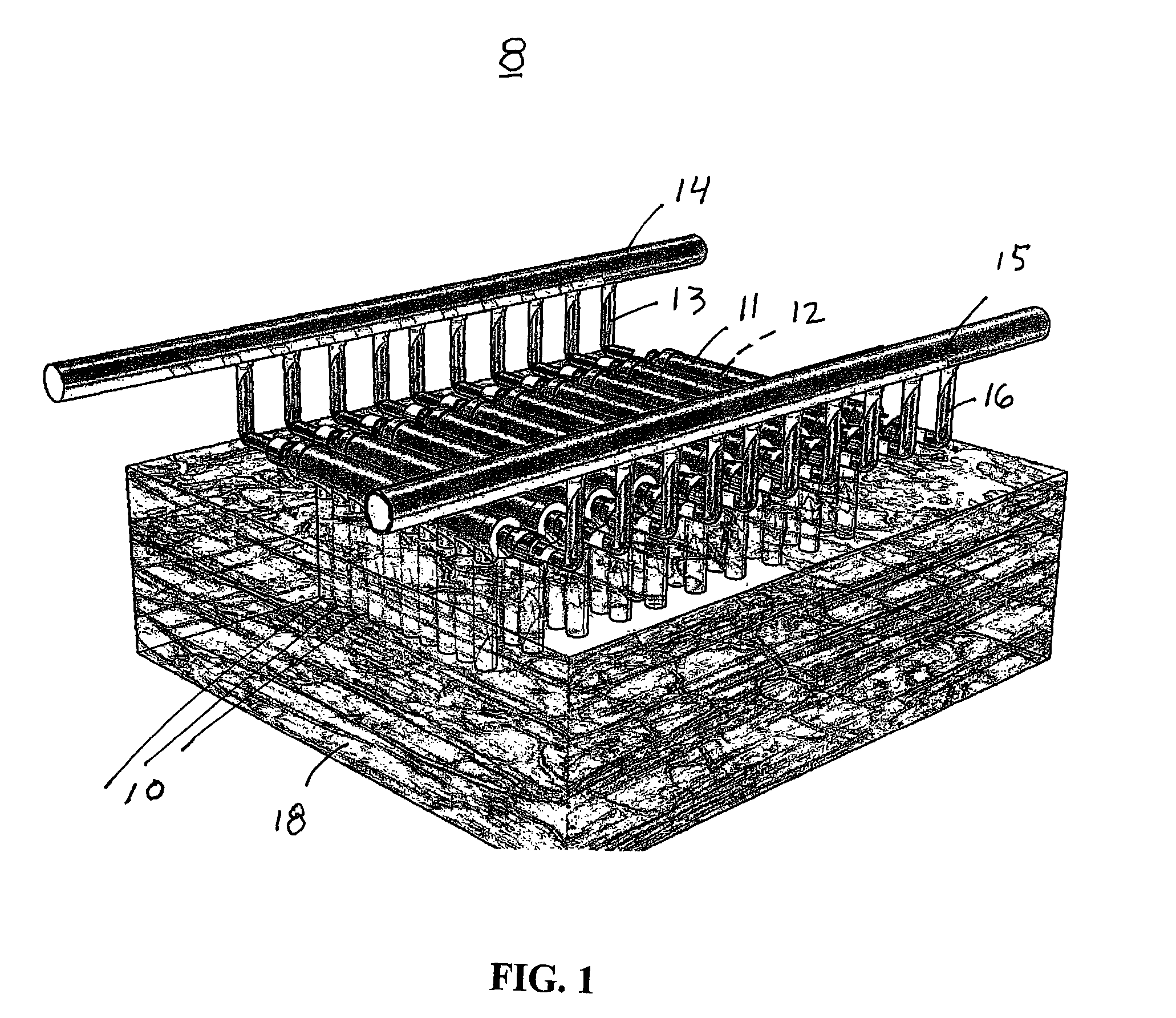
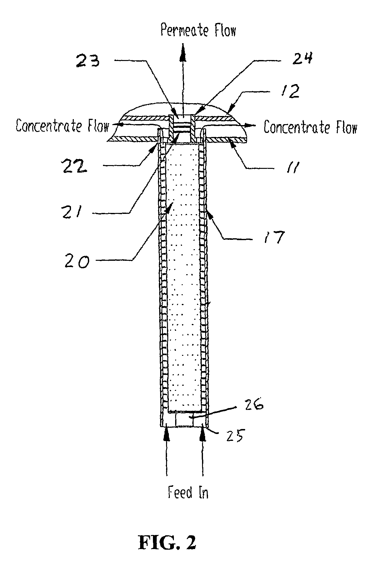
[0060]FIG. 10a illustrates another negative pressure filter embodiment 101 having a plurality of filter assemblies 10. Filter assemblies 10 are coupled to concentrate manifold 11 and permeate manifold 12. As shown in FIG. 10b, concentrate manifold 11 and permeate manifold 12 are generally parallel, but not concentric. At an opposite end, filter assemblies 10 each include a filter cap 100 having a plurality of apertures 102 sized to provide initial gross filtering of feed liquid to be filtered. For example, apertures 102 of cap 100 approximately 5 mm in diameter so that together cap 100 and cartridge 17 can remove particles ranging from about 6 mm to 0.3 microns.

[0061]FIG. 10b is a cross-sectional view of embodiment 101 taken along lines 11-11 of FIG. 10a. In the illustrated embodiment, cap 100 and filter cartridge 20 are permanently connected and are replaced together during a routine cartridge 20 exchange procedure. Cap 100 may be mechanically connected to filter housing 17, such a...

embodiment 120

[0063]FIG. 12 illustrates an embodiment 120 having a plurality of filter units 101 of FIG. 10a. Filter units 101 are coupled between concentrate line 14 and filtrate line 15. Lines 14, 15 are coupled to other lines (not shown) to transport the filtrate and concentrate out of the feed liquid tank. As described above, a filtration system would typically utilize one or more pumps, valves, controllers, etc. to control fluid flow through filter assemblies 10 during both a filtration procedure and a back-wash procedure.

[0064]Liquid to be filtered enters filter assemblies 10 through apertures 102 of caps 100. Embodiment 120 is adapted to be submerged within a tank of feed water. Cartridges 20 can be replaced by lowering the feed liquid level to expose the upper ends of filter housings 17, allowing caps 100 and cartridges 20 to be replaced.

[0065]Filtration system embodiment 120 of FIG. 12 may be supported upon a floor of a feed liquid tank or may be held on a frame (not shown) within the ta...


PUM

PropertyMeasurementUnit
pressuresaaaaaaaaaa
diameteraaaaaaaaaa
diameteraaaaaaaaaa

Abstract

A filter system and method of filtering a feed liquid utilizing a combined plurality of filter assemblies. Each filter assembly includes a filter housing, a filter cartridge and a spiral passageway for imparting secondary flow currents, particularly Dean-Flow currents, to fluid flowing within the spiral passageways to prevent particulate build-up on filter surfaces so as to extend filter life and duration between replacement. The filter system can be operated within positive or negative pressure filtration processes. A dual-stage filtration process utilizing a cap filter and a cylindrical depth filter is also disclosed.

Description

CROSS-REFERENCE TO RELATED APPLICATIONS[0001]This application claims the benefit of U.S. Provisional Application No. 60 / 731,320, filed Oct. 28, 2005, said application being incorporated by reference herein.TECHNICAL FIELD[0002]The present invention relates to filter systems and more particularly to a filtration system combining cross-flow currents and secondary flow currents such as Dean-Flow currents to assist in surface cleaning of the filter cartridge.BACKGROUND OF THE INVENTION[0003]In a typical fluid filtration application, cylindrical depth filters are housed within pressure vessels. During the filtration process the vessel is pressurized to force the fluid through the depth filter media. As the fluid flows through the filter, particles are trapped by the fibers that make up the depth filter media. The fluid that has been filtered (the “filtrate”) is then forced from the filter housing by the pressure within the vessel.[0004]FIG. 23 illustrates a known filtration device consis...

Claims


Application Information

Patent Timeline
Patent Type & Authority Patents(United States)
IPC IPC(8): B01D63/00B01D61/00
CPCB01D61/025B01D61/145B01D61/147B01D63/00B01D63/06B01D61/027C02F1/44B01D2313/08B01D2313/10B01D2313/20B01D2315/02B01D2317/022B01D2317/04B01D2321/04B01D2321/12B01D2321/18B01D2321/2008B01D2313/203
Inventor KOPP, CLINTON V.YU, GUANGHUAJEN, CHANG-WIE
Owner DUAL VORTEX MICROFILTRATION
Why Eureka
Try Eureka