
Method for generating a three-dimensional model of a roof structure

a three-dimensional model and roof structure technology, applied in the field of image processing systems, can solve the problems of laborious and costly process of generating a three-dimensional scene from a known image, and inability to construct such models from images alone,

Active Publication Date: 2010-06-01
SRI INTERNATIONAL
View PDF15 Cites 206 Cited by
  • Summary
  • Abstract
  • Description
  • Claims
  • Application Information

AI Technical Summary

Benefits of technology

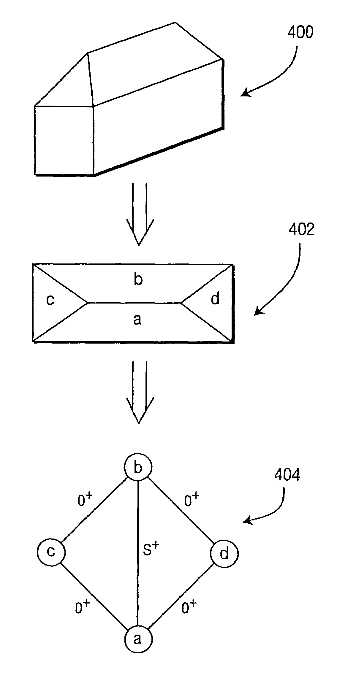
[0011]A similar process is performed to point clouds that are representative of indoor spaces to model a room and its contents (e.g., furniture). Specifically, the point cloud is processed to determine the ceiling and floor planes. The points in the point cloud that lie in the ceiling and floor planes are removed from the point cloud and the remaining points are processed to determine planar structures that define the furniture and other objects within the room. These structures are extruded to the floor plane to create furniture models. Texture can then be added to the planes to achieve a realistic, three-dimensional model of the indoor scene.

Problems solved by technology

Currently, constructing such models from images alone is a labor intensive process involving skilled photogrammetrists and graphic artists.
Thus, the process of generating a three-dimensional scene from a known image is labor intensive and costly.

Method used


Image

  • Method for generating a three-dimensional model of a roof structure
  • Method for generating a three-dimensional model of a roof structure
  • Method for generating a three-dimensional model of a roof structure

Examples


Embodiment Construction

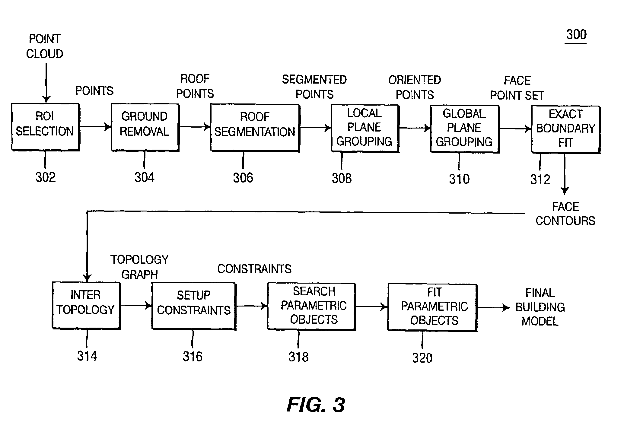
[0023]The present invention is a method and apparatus for automatically producing three-dimensional models of a scene. The source of data from which the model is created is a LIDAR point cloud produced by a LIDAR system.

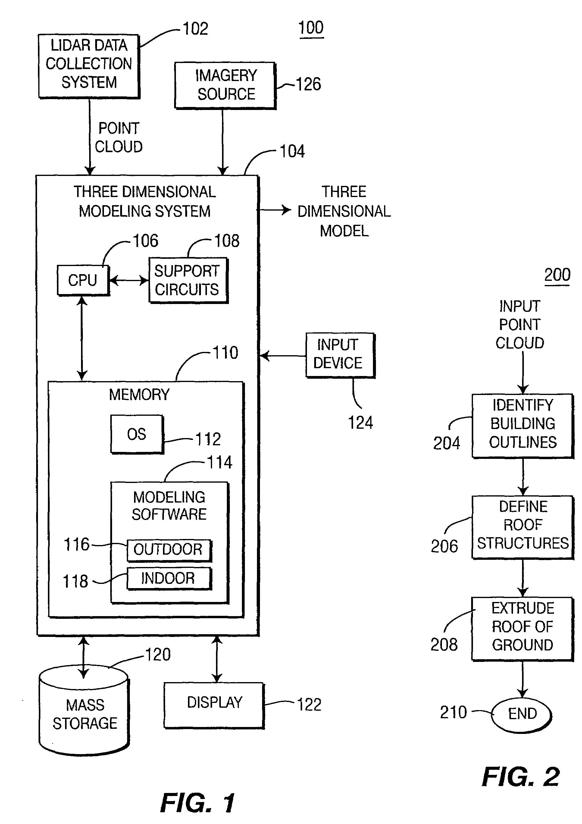
[0024]FIG. 1 depicts a block diagram of a system 100 comprising a LIDAR data collection system 102 and a three-dimensional modeling system 104. The LIDAR data collection system 102 is a commercially available LIDAR system that scans a scene and produces a point cloud representation of the scene. Each point within the point cloud represents an (x,y) coordinate and a depth from the LIDAR unit. Alternatively, a polar coordinate system may be used having a point defined by azimuth and elevation angles and a depth relative to the LIDAR unit.

[0025]The three-dimensional modeling system 104 is coupled to a variety of support components including a mass storage unit 120 for storing data, a display 122 for displaying information to a user 122, an imagery source 126 for providi...


PUM


Abstract

A method and apparatus for automatically generating a three-dimensional computer model from a “point cloud” of a scene produced by a laser radar (LIDAR) system. Given a point cloud of an indoor or outdoor scene, the method extracts certain structures from the imaged scene, i.e., ceiling, floor, furniture, rooftops, ground, and the like, and models these structures with planes and / or prismatic structures to achieve a three-dimensional computer model of the scene. The method may then add photographic and / or synthetic texturing to the model to achieve a realistic model.

Description

CROSS-REFERENCE TO RELATED APPLICATIONS[0001]This application claims benefit to U.S. provisional patent application Ser. No. 60 / 602,354, filed Aug. 18, 2004, and U.S. provisional patent application Ser. No. 60 / 693,718, filed Jun. 24, 2005, which are both herein incorporated by reference.GOVERNMENT RIGHTS IN THIS INVENTION[0002]This invention was made with U.S. government support under contract number N61339-03-C-0090. The U.S. government has certain rights in this invention.BACKGROUND OF THE INVENTION[0003]1. Field of the Invention[0004]Embodiments of the present invention generally relate to image processing systems and, more particularly, to a method and apparatus for creating three-dimensional models of scenes.[0005]2. Description of the Related Art[0006]The past decade has witnessed the emergence of three-dimensional graphics technology applied to various applications in commercial, military, and entertainment areas. This is been possible due to the advances in computing power, ...

Claims


Application Information

Patent Timeline
Patent Type & Authority Patents(United States)
IPC IPC(8): G06T17/00
CPCG06T17/20G06T17/00
Inventor VERMA, VIVEKKUMAR, RAKESHHSU, STEPHEN CHARLESSAWHNEY, HARPREET
Owner SRI INTERNATIONAL
Learn More