

Transceiver module with collapsible fingers that form a sealed EMI shield
- Summary
- Abstract
- Description
- Claims
- Application Information
AI Technical Summary
Benefits of technology
Problems solved by technology
Method used
Image

Examples
Embodiment Construction
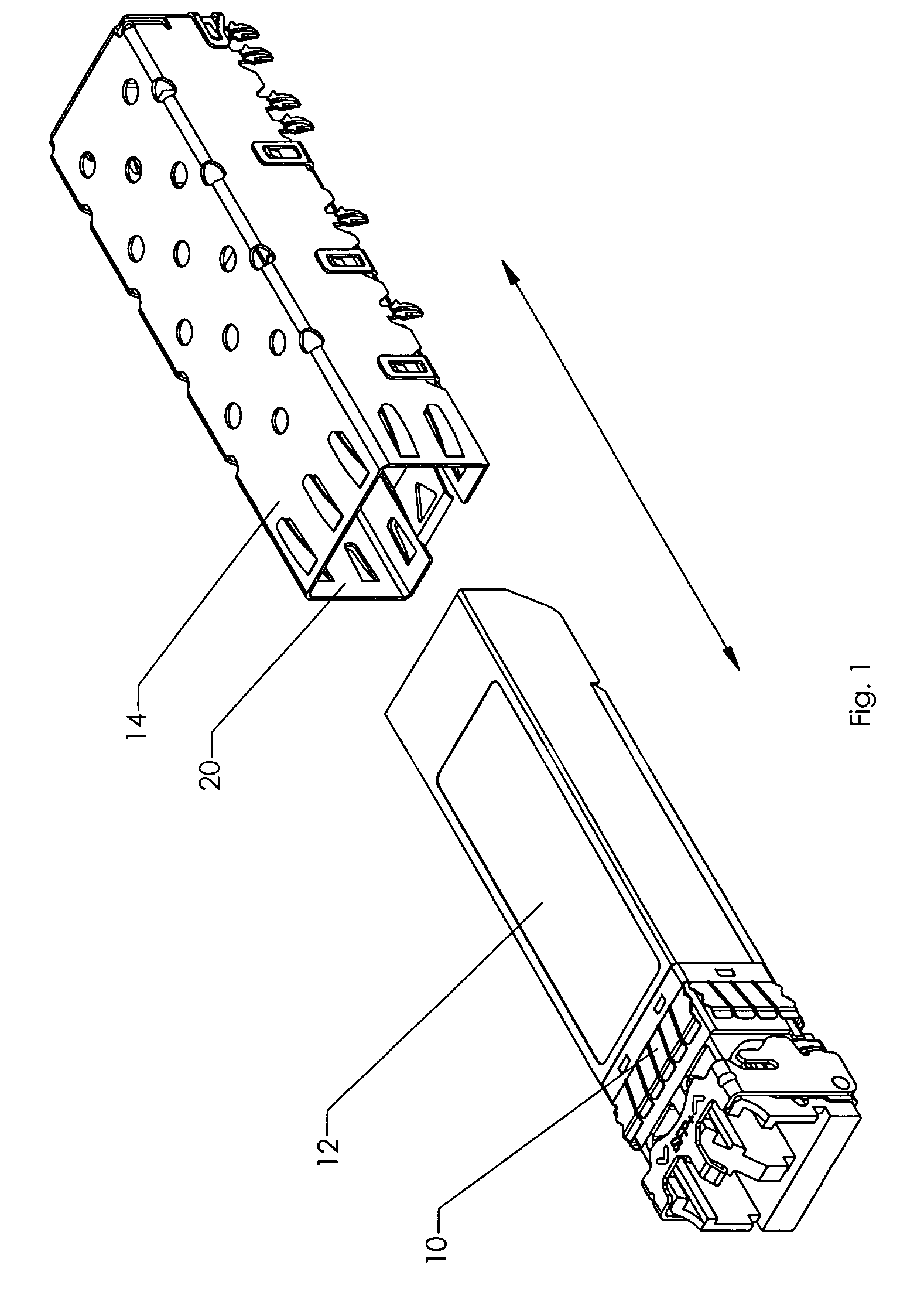
[0019]The present invention is an EMI shield 10 for a transceiver module 12. The transceiver module 12 is received in a cage 14 mounted on a PCB (not shown). The EMI shield 10 comprises a plurality of flexible fingers 16 that are mounted around the entire perimeter of the front portion 18 of the module 12. The front portion 18 of the transceiver module 12 is that portion that is surrounded by the mouth 20 of the cage 14 when the module 14 is in the installed position. In all applications, this area need to be protected by EMI shielding.
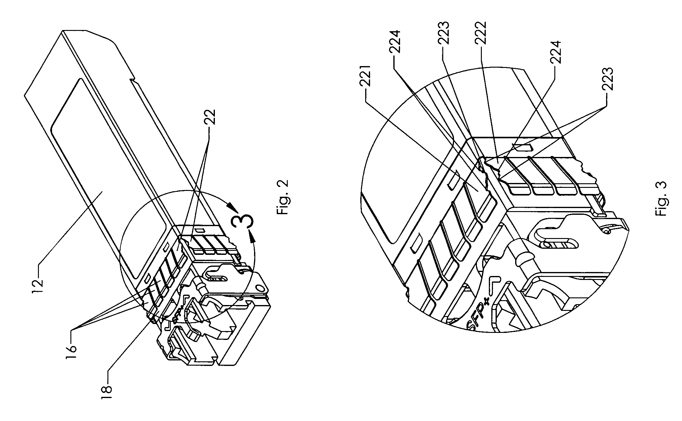
[0020]In the preferred embodiment, each finger 16 comprises a base 161 that is attached to the module 12. The fingers 16 extend slightly away from the body of the module 12 so that an interference fit with the cage 14 is created. A free end 162 of each finger 16 is angled downward to ensure that the fingers 16 do not catch on the mouth 20 of the cage 14 when the transceiver module 12 is inserted into the cage 14.
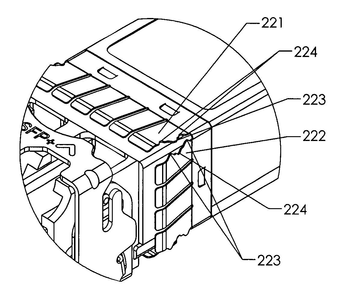
[0021]Referring now chiefly to FIGS. 3 ...
PUM
 Abstract
Description
Claims
Application Information