
Area management system

a management system and area technology, applied in the field of area management systems, can solve the problems of degrading the reception quality of wireless wireless terminals on the boundary of sub-areas, and achieve the effects of improving the reception quality of wireless terminals, saving time resources, and avoiding unnecessary use of wireless bands

Inactive Publication Date: 2010-06-01
HITACHI LTD
View PDF2 Cites 1 Cited by
  • Summary
  • Abstract
  • Description
  • Claims
  • Application Information

AI Technical Summary

Benefits of technology

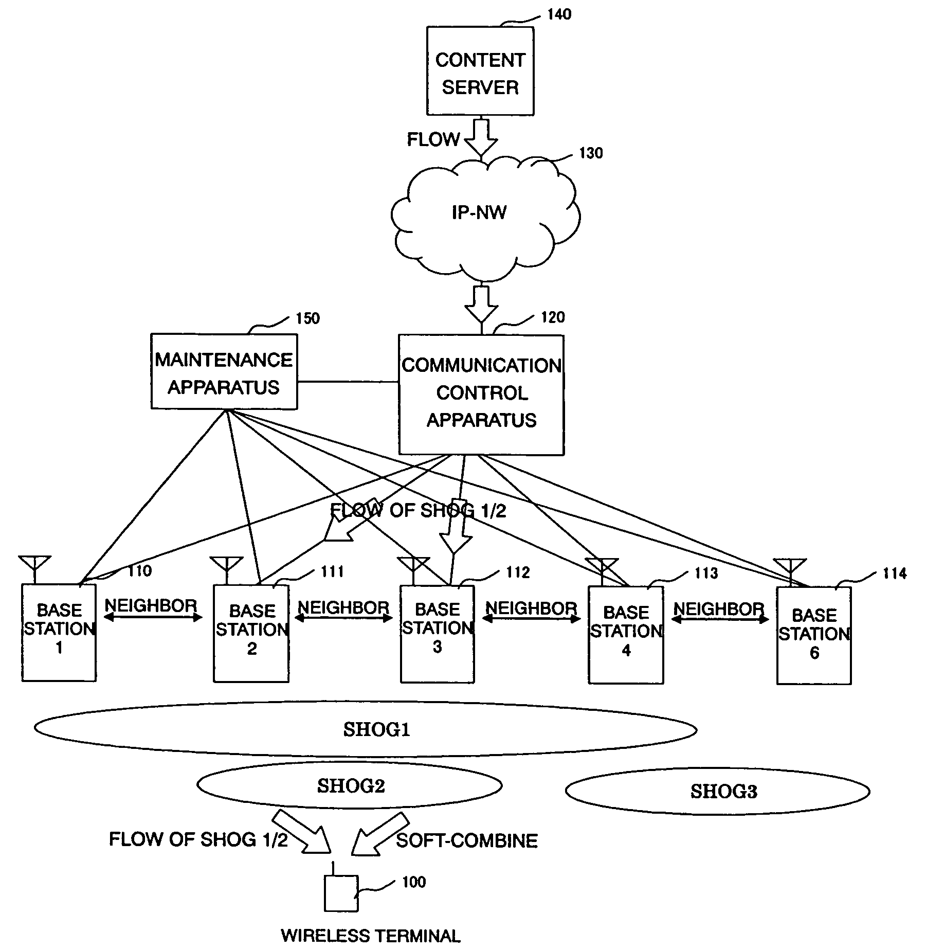
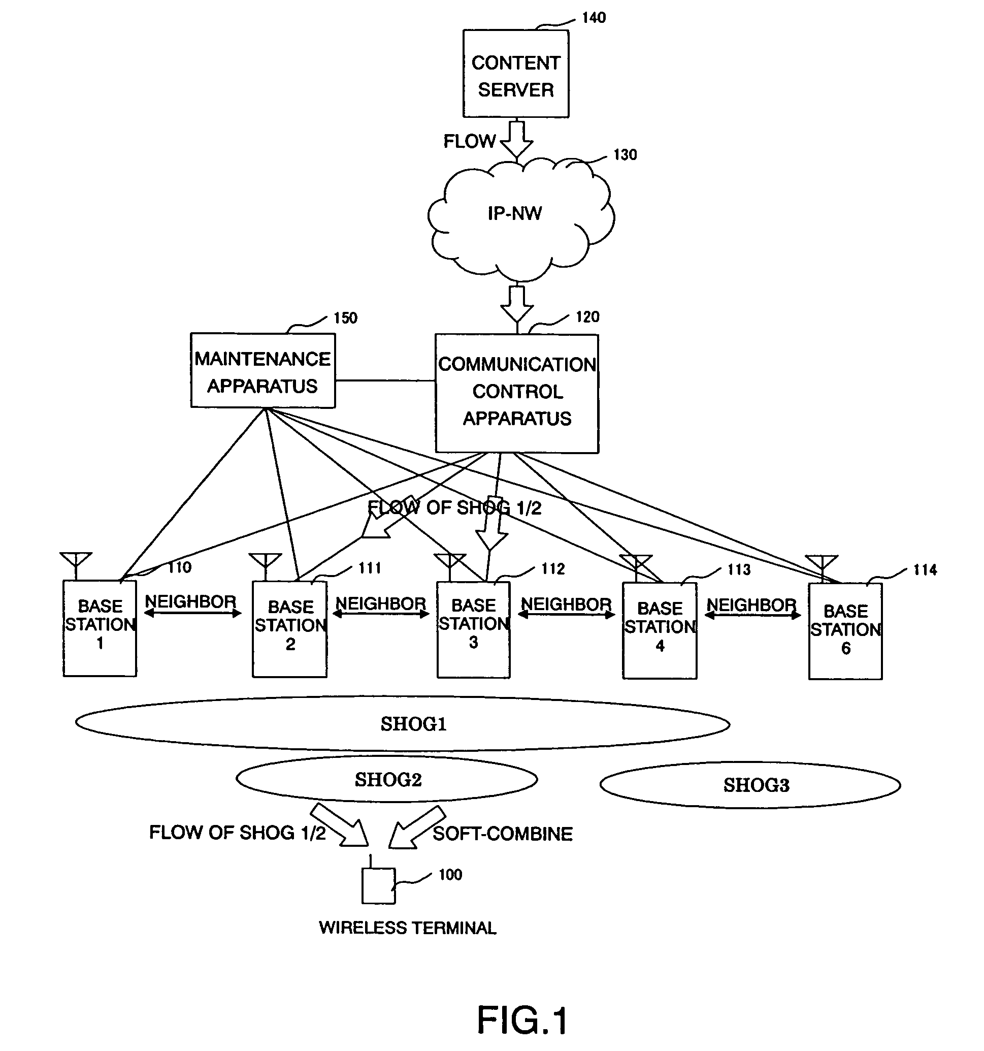
This approach enhances wireless band usage efficiency, prevents single flows from being transmitted across multiple areas, and enables soft-combining of data among sectors, improving reception quality and increasing the overall number of flows that can be sent in the system.

Problems solved by technology

This method of synchronizing all the sectors of the wireless base stations by the communication control apparatus, however, causes a problem.
If a flow which must be sent in several sub-areas is sent to a wireless terminal, soft-combine is impossible in the sub-areas, and the wireless reception quality is degraded on the boundary of the sub-areas.

Method used


Image

  • Area management system
  • Area management system
  • Area management system

Examples


first embodiment

[0104]FIG. 10 is a diagram showing a sequence for implementing area management of a

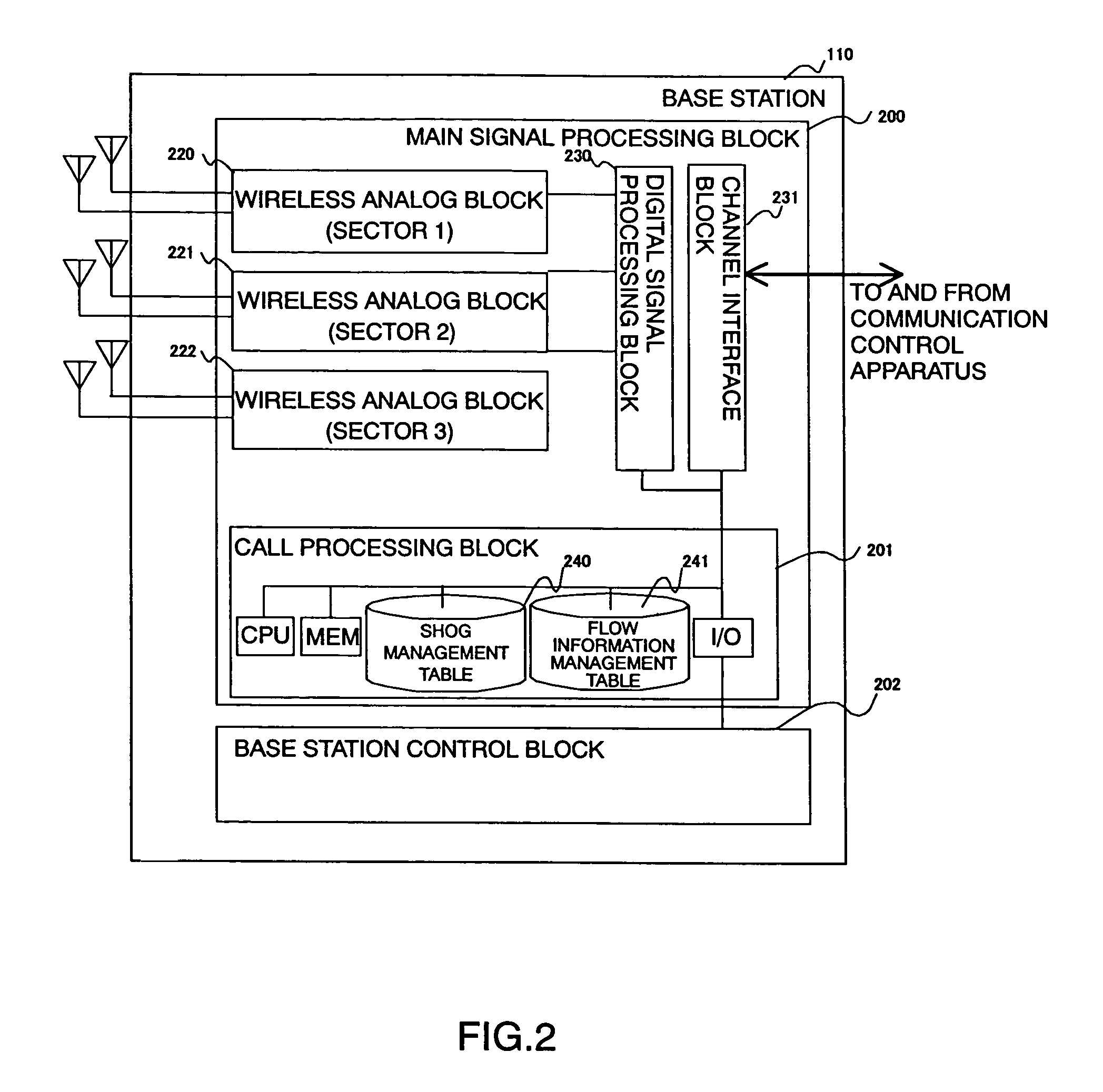
[0105]The initial state of the embodiment is as follows: The data of the SHOG management tables 240 in the wireless base stations 112, 111, and 113 is specified as shown in FIG. 6 (the same data can be specified), and nothing is specified in the flow information management tables 241 of the wireless base stations 112, 111, and 113. The data of the flow management table 301 on the communication control apparatus 120 is specified as shown in FIG. 8, and nothing is specified in the resource management table 302 of the communication control apparatus 120. Each of the wireless base stations may have just one sector.

[0106]The wireless terminal 100 or the maintenance apparatus 150 sends a flow delivery request message to the wireless base station 112, specifying the flow ID of a flow to be delivered (in step 1010). The flow IDs and the flows to be sent to the wireless terminal 100 are associated in a one-to-...

second embodiment

[0115]FIG. 13 is a diagram showing a sequence for implementing area management of a

[0116]The initial state of the embodiment is as follows. The data of the SHOG management table 240 of the wireless base station 112 is specified in advance as shown in FIG. 6, for instance, and nothing is specified in the flow information management table 241 of the wireless base station 112. The data of the flow management table 301 of the communication control apparatus 120 is specified in advance as shown in FIG. 8, for instance, and nothing is specified in the resource management table 302 of the communication control apparatus 120.

[0117]The wireless terminal 100 or the maintenance apparatus 150 sends a flow delivery request message to the wireless base station 112, specifying the flow ID of a flow to be delivered in sector “a” (in step 1010′).

[0118]Steps 1240 to 1051 are executed in the same way as described in “3. Operation 1.” When the flow delivery request is received from the communication co...


PUM


Abstract

A transmission area is specified flexibly in accordance with the contents of a flow. An area identification number (SHOG) is specified for each interlaced stream of wireless base stations. The same flow is sent at the same timing (or substantially at the same timing) in the interlaced stream specified for the same SHOG. A wireless terminal determines a neighbor sector or a neighbor wireless base station sending the same flow, in accordance with information given from the wireless base stations, and receives and combines the flows.

Description

BACKGROUND OF THE INVENTION[0001]1. Field of the Invention[0002]The present invention relates to area management systems, and more specifically, to an area management system for a multicast service for allowing a plurality of wireless terminals to receive a flow transmitted from a wireless base station, in a wireless system for conducting voice or data communication, with control information sent from the wireless base station.[0003]2. Description of the Related Art[0004]With the proliferation of broadband, technological advances of routers and other apparatuses, the growing need of end users for receiving broadband streaming pictures and the like, and advances in producer-driven solutions, the multicast technology, which can broadcast data with a fewer communication resources than the unicast technology, has been attracting growing interest in the communication field. With the multicast technology, a router placed between a server and clients makes a required number of duplicates o...

Claims


Application Information

Patent Timeline
Patent Type & Authority Patents(United States)
IPC IPC(8): H04W4/00H04W4/06H04W28/02H04W88/08H04W88/14H04W88/18
CPCH04W72/121H04L45/16H04W28/02H04W36/18H04W88/18H04W88/08H04W88/14H04W40/24
Inventor YOSHIDA, AKIHIKOMAZAWA, SHIROTAKAHASHI, YOSUKETAKAYANAGI, DAIGO
Owner HITACHI LTD
Learn More