X-ray imaging apparatus

a technology of x-ray imaging and x-ray, which is applied in the direction of material analysis using wave/particle radiation, instruments, applications, etc., can solve the problems of reducing the operability of the x-ray imaging apparatus, generating an effective image for diagnostics, and reducing the operability of the vertical position setting. , to achieve the effect of reducing safety, generating effective images for diagnostics, and reducing the operability of the vertical position setting

Inactive Publication Date: 2010-06-01
CANON KK
View PDF10 Cites 115 Cited by
  • Summary
  • Abstract
  • Description
  • Claims
  • Application Information

AI Technical Summary

Benefits of technology

[0018]The present invention is directed to an X-ray imaging apparatus which is capable of taking a general still image as well as a CT image, and which is useful in generating an effective image for diagnostics without reducing operability of the vertical position setting of the X-ray imaging unit and, further, without reducing safety.

Problems solved by technology

However, since radiation detectors of the aforementioned imaging apparatuses are large-sized two-dimensional plane sensors, these imaging apparatuses are generally expensive.
As a result, ease of operability of the X-ray imaging apparatus is reduced.
A similar problem occurs when the image taking mode is changed.
Thus, if an imaging apparatus including a height-adjustable X-ray imaging unit moves the X-ray imaging unit up and down during the CT imaging, proper images may not be obtained and therefore reconstruction becomes difficult.
Since the conventional apparatus does not include a method for prohibiting the up-and-down movement during the rotation, there is a possibility that the X-ray imaging unit moves up-and-down during the image taking.

Method used


Image

  • X-ray imaging apparatus
  • X-ray imaging apparatus
  • X-ray imaging apparatus

Examples


Embodiment Construction

[0027]Various exemplary embodiments, features, and aspects of the invention will now be described in detail with reference to the drawings.

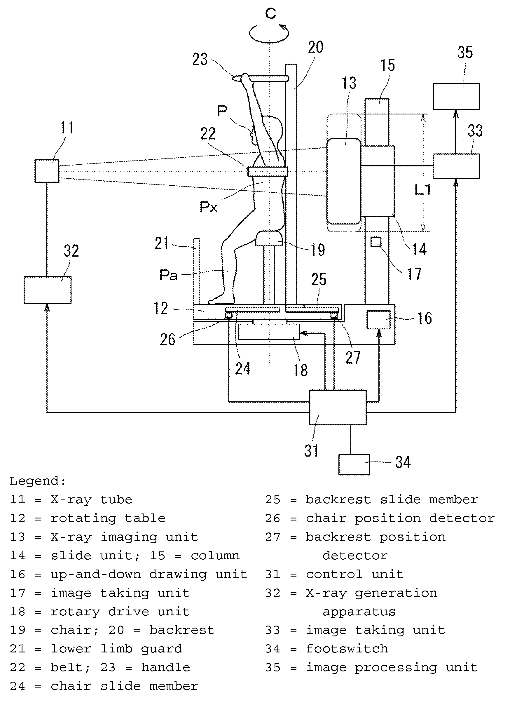
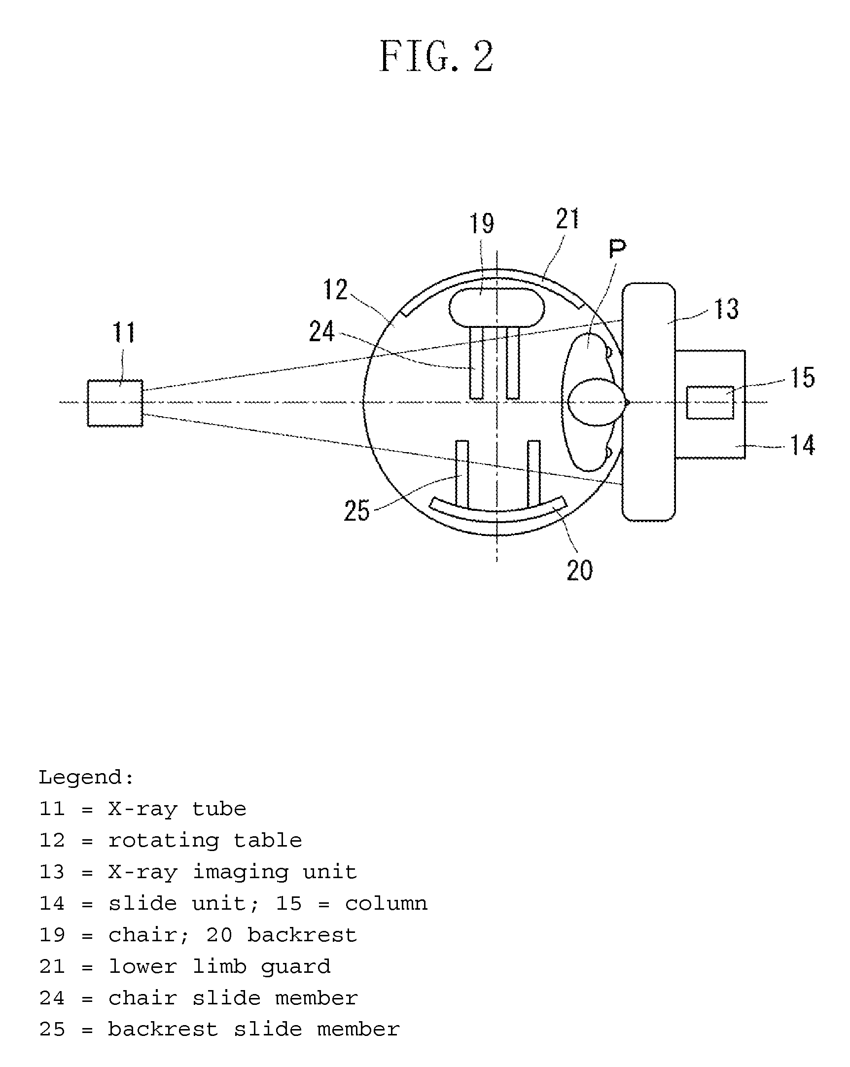
[0028]FIG. 1 illustrates a configuration of an X-ray imaging apparatus in a CT imaging mode in which the subject (P) is rotated during image taking according to an exemplary embodiment of the present invention. In front of an X-ray tube 11, an X-ray imaging unit 13 which is, for example, a plane sensor, is arranged facing the X-ray tube 11. A subject P on a rotating table 12 is positioned between the X-ray tube 11 and the X-ray imaging unit 13. The rotating table 12 is rotatable 360 degrees. The X-ray imaging unit 13 is moveably attached to a column 15 through a slide unit 14. The slide unit 14 is driven up-and-down by an up-and-down drive unit 16. The lowest position of the X-ray imaging unit 13 can be detected by an image taking unit position detector 17.

[0029]The rotating table 12 is supported by a rotary drive unit 18. A chair 19 on which the...


PUM

PropertyMeasurementUnit
computed tomographyaaaaaaaaaa
CTaaaaaaaaaa
circumferenceaaaaaaaaaa

Abstract

An X-ray imaging apparatus includes an X-ray imaging unit, rotating unit configured to rotate a subject about an axis of rotation relative to the X-ray imaging unit, supporting unit configured to support the subject, and a limiting unit configured to limit the range in which the X-ray imaging unit is moveable along the axis of rotation depending on the position of the supporting means relative to the axis of rotation.

Description

BACKGROUND OF THE INVENTION[0001]1. Field of the Invention[0002]The present invention relates to an X-ray imaging apparatus configured to generate an X-ray image of a subject using an X-ray beam passing through the subject.[0003]2. Description of the Related Art[0004]Conventionally, a computed tomography (CT) apparatus for generating a three-dimensional cross-sectional image of a subject is used in the medical area. In order to obtain the three-dimensional cross-sectional image, radiation emitted to the subject from a circumference of the subject is detected and converted into an image signal after it passes through the subject. Then, through reconstruction processing, the image signal is converted into a three-dimensional cross-sectional image.[0005]A helical scanning CT apparatus is a type of apparatus which is commonly used today. The helical scanning CT apparatus is configured such that a radiation source and a radiation detector, configured as a pair, rotate helically around th...

Claims


Application Information

Patent Timeline
Patent Type & Authority Patents(United States)
IPC IPC(8): A61B6/00G01N23/00G21K1/12H05G1/60
CPCA61B6/4482A61B6/102
Inventor KOBAYASHI, MASAAKI
Owner CANON KK
Why Eureka
Try Eureka