Unlock instant, AI-driven research and patent intelligence for your innovation.

Future execution prefetching technique and architecture

a technology of future execution and prefetching, applied in the field of future execution prefetching technique and architecture, can solve the problems of unpredictability of many important load addresses and cached data, and achieve the effects of increasing software complexity and cost, increasing contention, and improving the performance of individual computation threads

Active Publication Date: 2010-06-01
CORNELL RES FOUNDATION INC
View PDF10 Cites 19 Cited by
  • Summary
  • Abstract
  • Description
  • Claims
  • Application Information

AI Technical Summary

Benefits of technology

"The present invention provides a technique for improving memory access speeds during execution of a program thread by a processor core. This technique involves predicting the future values of data that will be needed by the original program thread and prefetching the data into memory. The prefetching is done by creating a modified version of the original program thread and executing it on a separate processor core. The technique takes advantage of the fact that most cache misses are caused by repeated executions of a small number of dynamic instructions. The use of future execution speeds up the rate of execution of most program threads and can be combined with other prefetching techniques to achieve even greater performance improvements. The future execution approach also allows for dynamic adjustment of the prefetching distance and cancellation of the prefetching activity if no resources are available."

Problems solved by technology
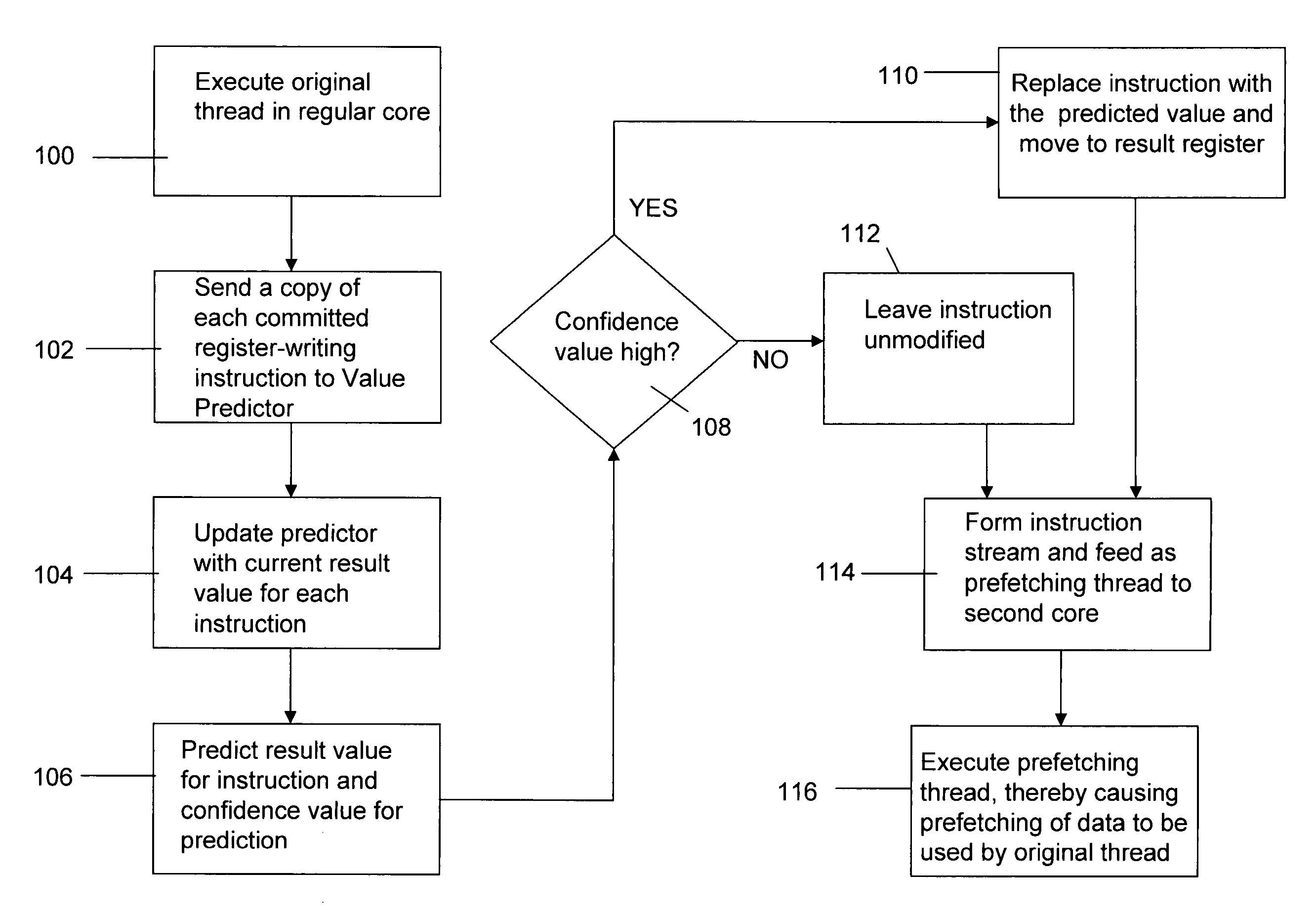
This technique inherently results in caching of data that is to be used by the original program thread at a future time.
However, many important load addresses are not directly predictable.
Fortunately, even if a missing load's address exhibits no regularity and is thus unpredictable, it is often possible to correctly predict the input values to its dataflow graph (backward slice) and thus to compute a prediction for the address in question.

Method used


Image

  • Future execution prefetching technique and architecture
  • Future execution prefetching technique and architecture
  • Future execution prefetching technique and architecture

Examples


Embodiment Construction

[0032]A detailed discussion of the implementation of the FE micro-architecture will be presented following a discussion of the quantitative analysis of the observations that inspired the present invention. One of the main program properties exploited by FE is that most load misses occur in “loops” with relatively short iterations. Note that any repetitively executed instruction is referred to as a “loop” instruction. The distance between the load instructions that cause an L2 cache miss and the previous execution of the same load instruction were evaluated. It was found from the quantitative analysis that on average from 70 to 80% of the misses occur in loops with iterations shorter than 1000 instructions. This observation suggests a prefetching approach in which each load instruction triggers a prefetch of the address that the same load is going to reference in the nth next iteration. Since in most cases the time between the execution of a load instruction and its next dynamic exec...


PUM


Abstract

A prefetching technique referred to as future execution (FE) dynamically creates a prefetching thread for each active thread in a processor by simply sending a copy of all committed, register-writing instructions in a primary thread to an otherwise idle processor. On the way to the second processor, a value predictor replaces each predictable instruction with a load immediate instruction, where the immediate is the predicted result that the instruction is likely to produce during its nth next dynamic execution. Executing this modified instruction stream (i.e., the prefetching thread) in another processor allows computation of the future results of the instructions that are not directly predictable. This causes the issuance of prefetches into the shared memory hierarchy, thereby reducing the primary thread's memory access time and speeding up the primary thread's execution.

Description

GOVERNMENT SPONSORSHIP STATEMENT[0001]This invention was made with Government support from the National Science Foundation (NSF) under grant numbers CNS-0125987 and CCF-0312966. The Government has certain rights in the invention.BACKGROUND OF THE INVENTION[0002]1. Field of the Invention[0003]The present invention relates in general to a prefetching technique referred to as future execution (FE) and associated architecture for accelerating execution of program threads running on microprocessors, particularly those of the multicore variety. Important data for each program thread is prefetched through concurrent execution of a modified version of the same thread, preferably using an available idle processor core that operates independently of the active core on which the original program thread is being executed.[0004]2. Description of the Background Art[0005]The cores of modern high-end microprocessors deliver only a fraction of their theoretical peak performance. One of the main reas...

Claims


Application Information

Patent Timeline
Patent Type & Authority Patents(United States)
IPC IPC(8): G06F12/00G06F13/00G06F13/28
CPCG06F9/3851G06F9/3832G06F9/3017G06F9/3455G06F9/30047G06F12/0862
Inventor BURTSCHER, MARTINGANUSOV, ILYA
Owner CORNELL RES FOUNDATION INC