
Apparatus on a flat card or roller card for textile fibres, such as cotton, synthetic fibres or the like, for removing short fibres

a technology of textile fibres and flat cards, applied in the direction of fibre cleaning/opening, textiles and paper, roughening, etc., can solve the problems of large proportion of such fibres, negative pressure and turbulence, and the separation of waste with the trash, so as to improve separation and discharge

Inactive Publication Date: 2010-06-08
TRUETZSCHLER GMBH & CO KG
View PDF14 Cites 0 Cited by
  • Summary
  • Abstract
  • Description
  • Claims
  • Application Information

AI Technical Summary

Benefits of technology

[0004]It is an aim of the invention to produce an apparatus of the kind described initially, which avoids or mitigates the said disadvantages and which in particular in a simple manner allows improved separation and discharge of short fibres from the fibre layer on the cylinder.
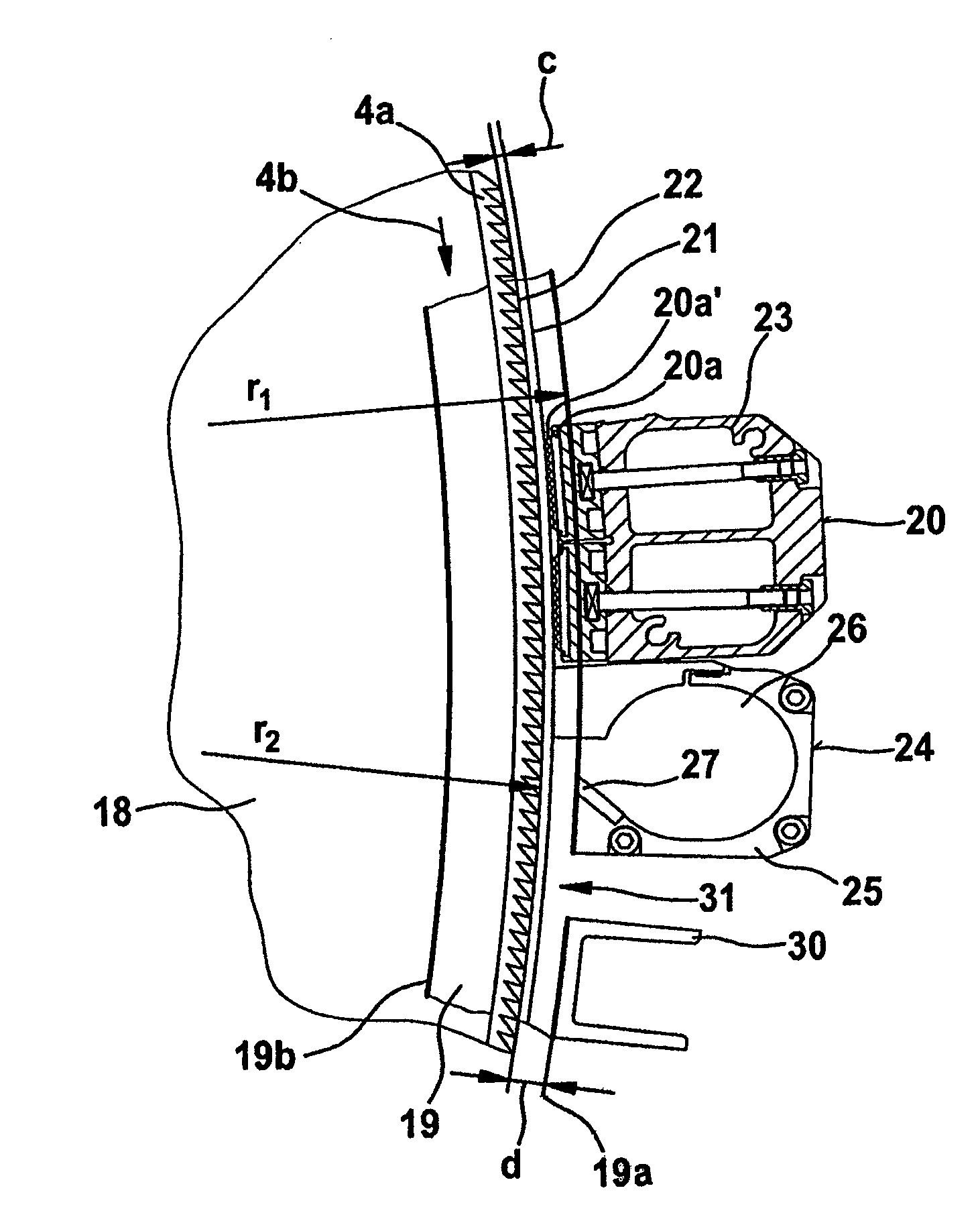
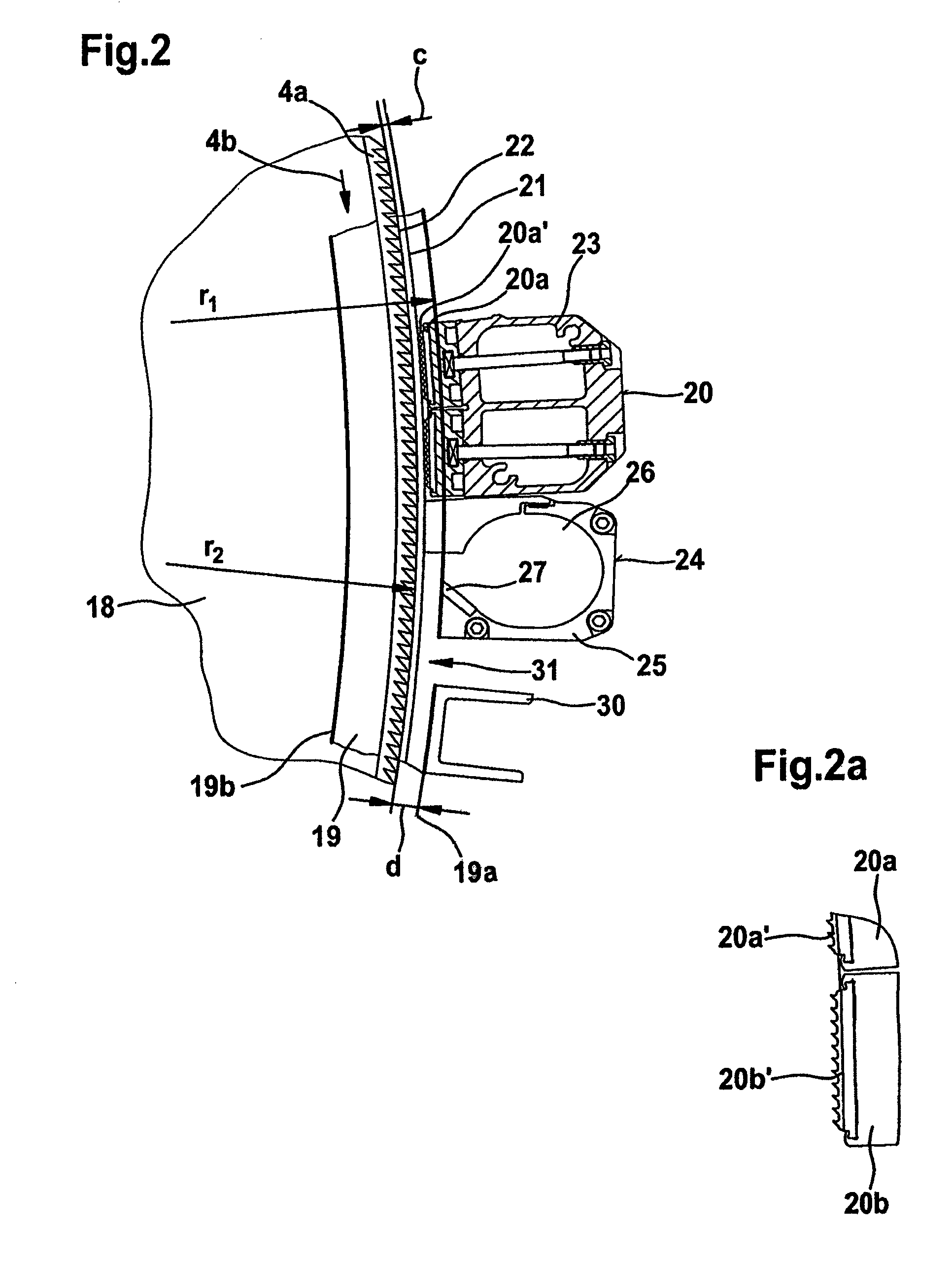
[0006]The features according to the invention allow a substantially improved separation and discharge of short fibres from the fibre layer on the cylinder. The fibres are present on the cylinder surface opened substantially down to individual fibres. In the arrangement of the invention an air flow can be guided in advantageous manner over the cylinder surface against the direction of rotation of the cylinder and separate the lighter short fibres from the good fibres and discharge them through the exhaust air opening. Because, with regard to the cylinder, the spacing of the covering between the exhaust air opening and the supply air opening is greater than the spacing of the covering upstream of the exhaust air opening, on the one hand there is a greater flow cross-section in the region in which the supply air can flow to the air exhaust opening, and on the other hand the narrow flow cross-section between the covering upstream of the air exhaust opening and the cylinder can form a barrier to the supply air. As a result, the fibre material is thoroughly cleaned of short fibres with high separated amounts and high proportions of short fibres in the waste.

Problems solved by technology

Downstream of the edge, a negative pressure and turbulence therefore develop, and are counterbalanced by the supply airflow.
The drawback is that a considerable portion of such fibres, which are supposed to remain in the processing process, commonly known as good fibres, are separated out together with the trash.
What is more, an unacceptable proportion of short fibres remains in the layer of fibres on the cylinder.
This leads all in all to unsatisfactory cleaning results, which gives rise to adverse effects in yarn production and to loss of yarn quality.

Method used


Image

  • Apparatus on a flat card or roller card for textile fibres, such as cotton, synthetic fibres or the like, for removing short fibres
  • Apparatus on a flat card or roller card for textile fibres, such as cotton, synthetic fibres or the like, for removing short fibres
  • Apparatus on a flat card or roller card for textile fibres, such as cotton, synthetic fibres or the like, for removing short fibres

Examples


Embodiment Construction

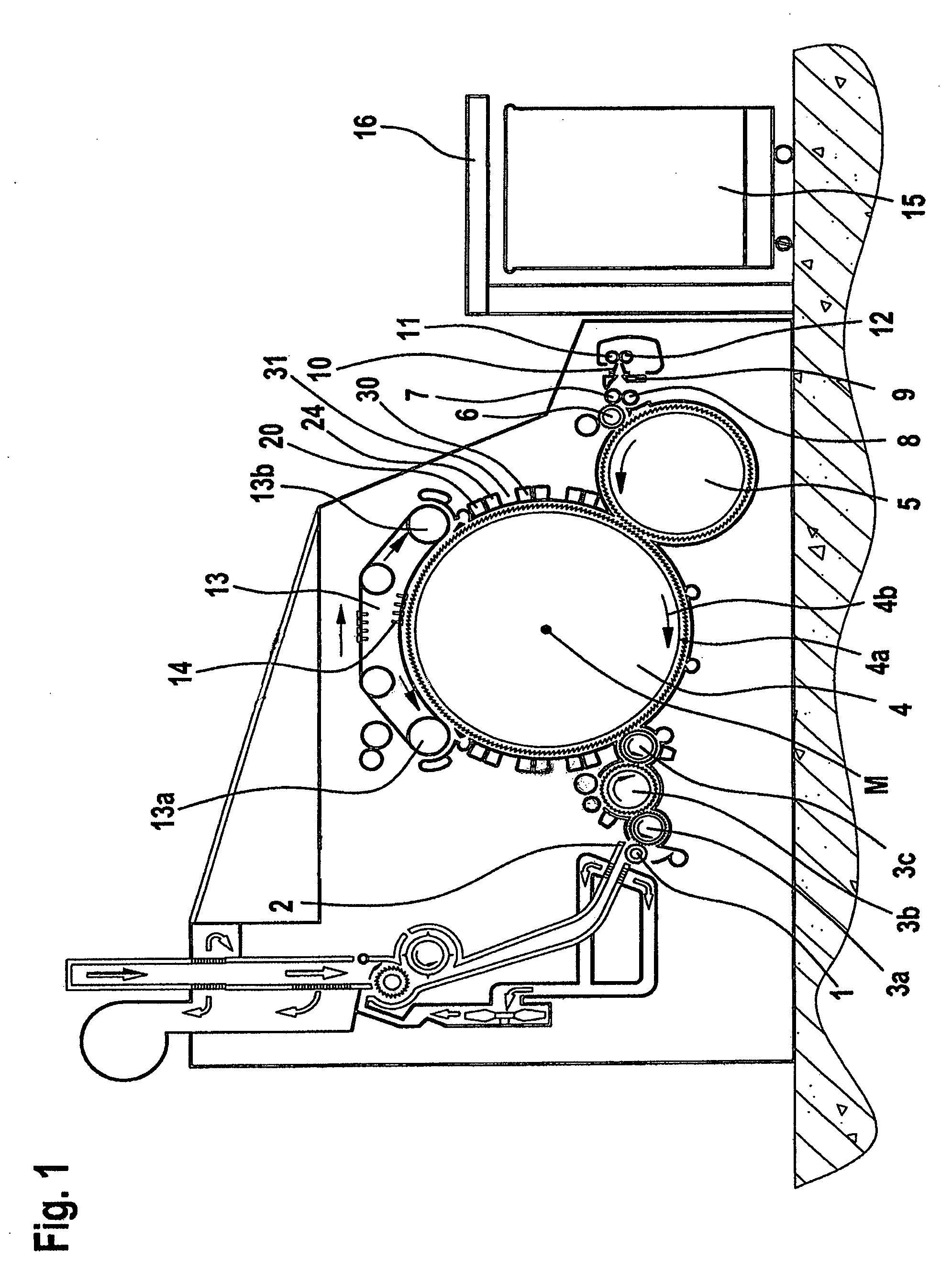
[0021]With reference to FIG. 1, a flat card, for example, a flat card TC 03 (Trade Mark) made by Trützschler GmbH & Co. KG. of Mönchengladbach, Germany has feed roller 1, feed table 2, licker-ins 3a, 3b, 3c, cylinder 4, doffer 5, stripping roller 6, squeezing rollers 7, 8, web-deflector 9, web funnel 10, take-off rollers 11, 12, revolving flat 13 with flat guide rollers 13a, 13b and flat bars 14, can 15 and can coiler 16. The directions of rotation of the rollers are shown by respective curved arrows. The letter M denotes the midpoint (axis) of the cylinder 4. The reference numeral 4a denotes the clothing and 4b denotes the direction of rotation of the cylinder 4. The arrow A denotes the working direction. The curved arrows drawn in the rollers denote the directions of rotation of the rollers. The cylinder 4 has a surface speed, for example, of 35 m / sec.

[0022]FIG. 2 shows a first embodiment of the invention, suitable for use in, for example, the card of FIG. 1. On each side of the c...


PUM

PropertyMeasurementUnit
suction pressureaaaaaaaaaa
surface speedaaaaaaaaaa
distanceaaaaaaaaaa

Abstract

An apparatus on a carding machine has a covering comprising work and cover elements lying opposite the clothing of a high-speed cylinder. There is, in succession, an air exhaust opening for the exit of air and an opening for entry of air, past which openings a flow of fibers and air is passed. To allow improved detachment and elimination of short fibers in a simple manner, the spacing of the covering upstream of the exhaust opening is smaller than the spacing of the covering between air exhaust opening and air inlet opening and an airflow flows against the direction of rotation of the cylinder along the surface of the cylinder and flows with short fibers through the air exhaust opening.

Description

CROSS-REFERENCE TO RELATED APPLICATION[0001]The present application claims priority from German Patent Application No. 10 2006 005 589.6 dated Feb. 6, 2006, the entire disclosure of which is incorporated herein by reference.BACKGROUND OF THE INVENTION[0002]The invention relates to an apparatus on a flat card or roller card for textile fibres such as cotton, synthetic fibres or the like, in which a covering comprising work and cover elements lies opposite the clothing of a high-speed cylinder. In one known apparatus—viewed in the direction of rotation of the cylinder—in succession there is an opening for the exit of air (exhaust airflow) and an opening for entry of air (supply airflow), past which openings a flow of fibres and air is passed, wherein, in relation to the cylinder, the spacing of the covering upstream of the exhaust air opening and the spacing of the covering downstream of the exhaust air opening are different.[0003]In EP 0 848 091 A1, a casing part with a deflector, an...

Claims


Application Information

Patent Timeline
Patent Type & Authority Patents(United States)
IPC IPC(8): D01G15/76
CPCD01G15/34D01G15/74
Inventor SAEGER, NICOLEFRIEDRICH, ROLANDHENSGEN, GERHARD
Owner TRUETZSCHLER GMBH & CO KG
Learn More