Semi-automatic dispenser for disposable cups

a dispenser and semi-automatic technology, applied in the direction of coin-freed apparatus, pile separation, application, etc., can solve the problems of affecting the manufacturing of components, shaft wear or material fatigue, etc., and achieve the effect of maintaining the whole ensemble adequately tigh

Inactive Publication Date: 2010-06-08
MOREIRA DE LIMA MAURO +1
View PDF14 Cites 7 Cited by
  • Summary
  • Abstract
  • Description
  • Claims
  • Application Information

AI Technical Summary

Benefits of technology

[0007]Another advantage is the fact that the system comprising the sliding diaphragm is designed to perform a sequence of angular movements, where: a) the first bottom cup will be completely separated from the subsequent cup; b) the stack of cups located above the first cup will remain firmly leaned, and only one cup—or the first bottom cup—will be released; c) the first cup, separated from the others, will be released through free fall and will remain positioned so that the user can pick it up easily; and d) that diaphragm will shut again the opening through which the cup was released, maintaining the inner section of the device completely isolated from the environment, avoiding inclusively the penetration of insects.
[0011]Hence, in this other preferred concretion, the modifications were created so that the mobile parts can operate through straight movements. Consequently, the ensemble efficiency is considerably improved, mainly due to the fact that the mentioned diaphragm does not use one point as shaft. The straight movements request only straight guides or fittings. In this way, possible points which could eventually exhibit easy wearing were eliminated.

Problems solved by technology

Eventually, this shaft can be subjected to wearing or material fatigue.
Consequently, this configuration impairs the component manufacturing.

Method used


Image

  • Semi-automatic dispenser for disposable cups
  • Semi-automatic dispenser for disposable cups
  • Semi-automatic dispenser for disposable cups

Examples


Embodiment Construction

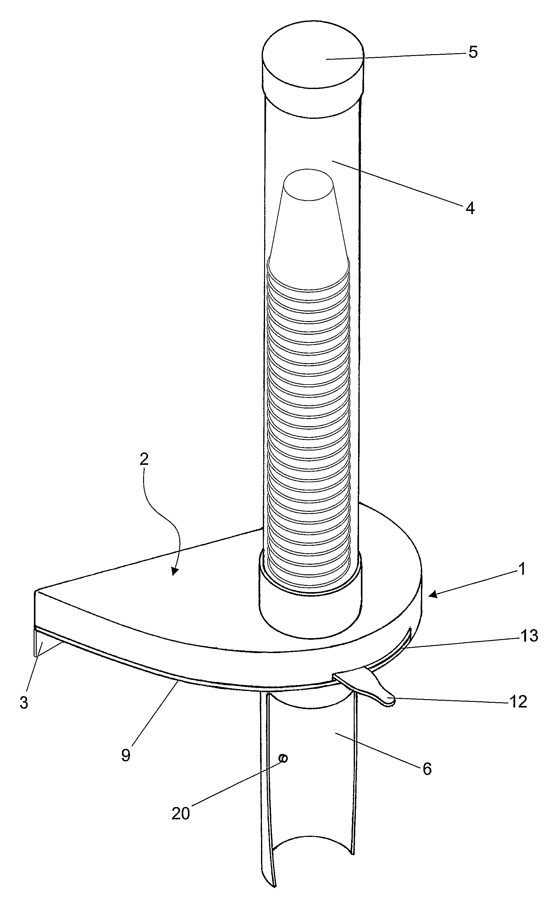
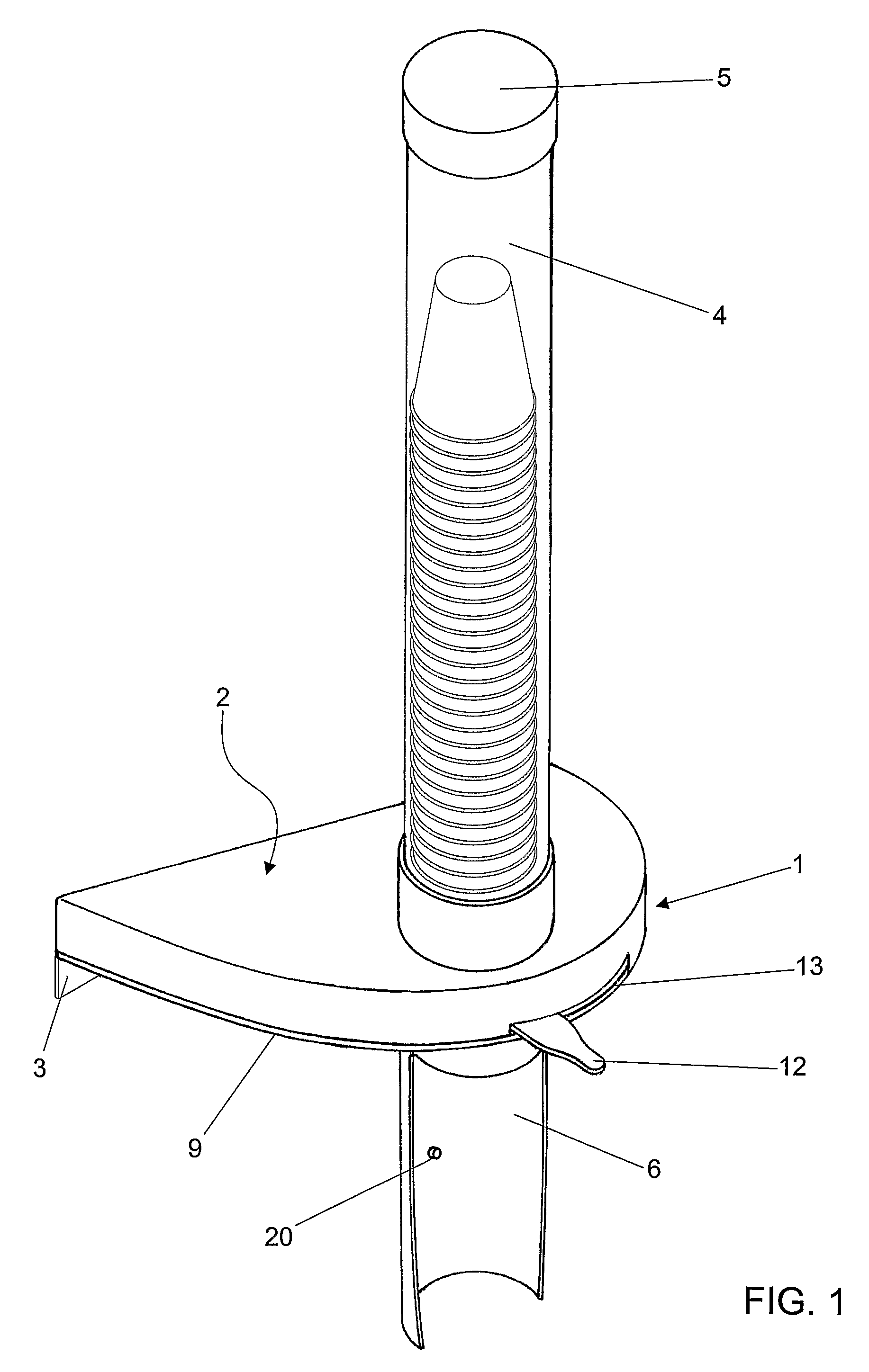
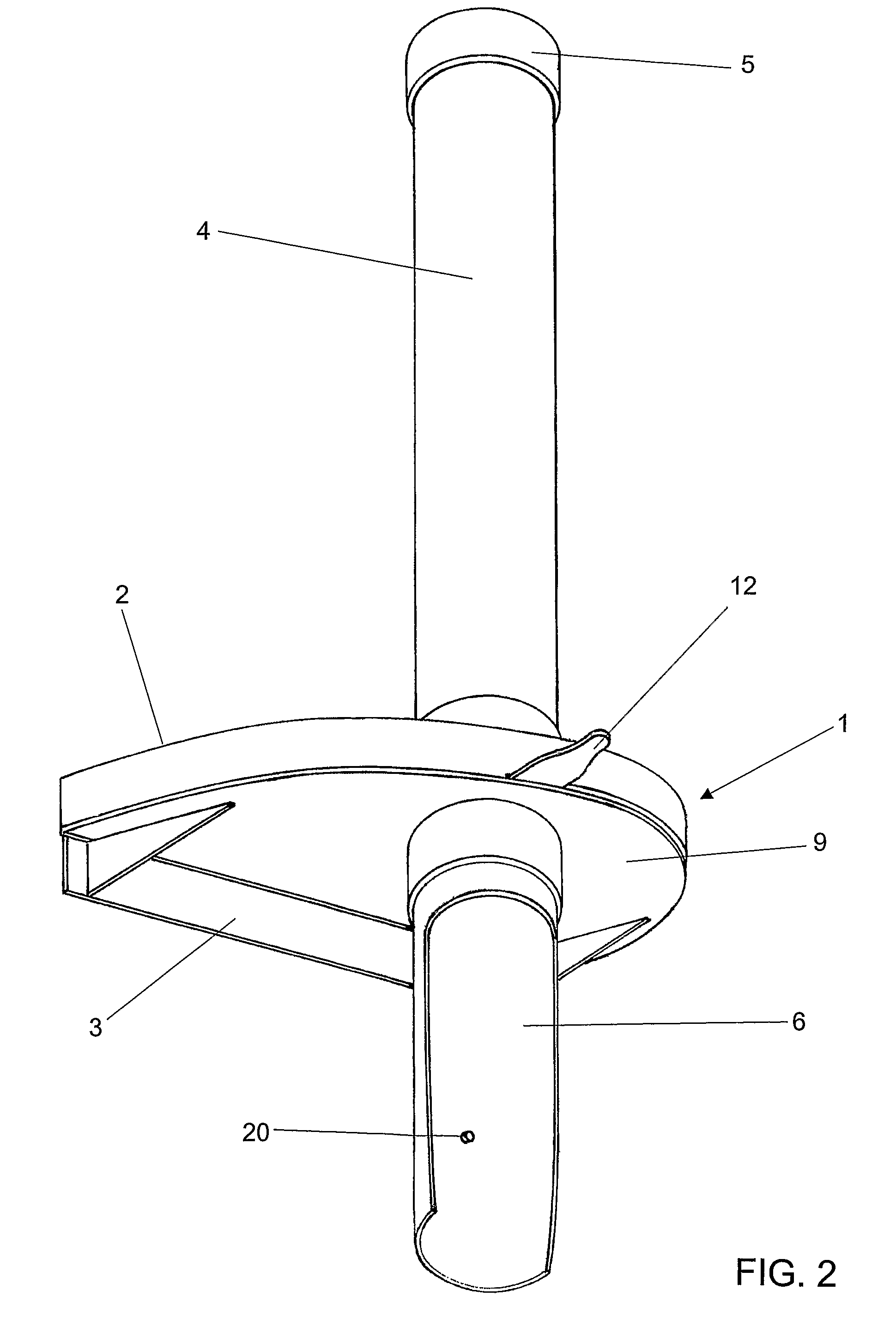
[0030]According to the illustrated in FIGS. 1 and 2, the present invention—in its first preferred concretion—comprises a semi-automatic dispensing device (1), defined as a box (2) exhibiting an half moon or semi-circular shape, whose straight section is facing the rear side, where it includes a fastening plate (3) for the ensemble in an adequate place, whilst the curved section is facing the front. Its superior section includes a vertically assembled tubular compartment (4), which should be preferably transparent, with a top lid (5). This configures the compartment for several common disposable cups, arranged with their mouths facing downwards. The bottom of this compartment is axially aligned with another ordinarily vertical and tubular and section (6), which constitutes the exit for the cups to be dispensed by the semi-automatic dispensing device (1).

[0031]The dispensing device (1), as already mentioned, comprises one box (2) exhibiting an half moon or semi-circular shape. As repr...


PUM


Abstract

Semi-automatic dispenser for disposable cups, comprising a semi-automatic dispensing mechanism (1-50), defined by a box (2-51) having in its upper section a tubular drawer (4-43) for the accommodation of several common disposable cups (C), arranged as a stack with their mouths facing downwards, and further, each cup is expected to be dispensed in a bottom drawer (6-62).

Description

CROSS REFERENCE TO RELATED APPLICATIONS[0001]Applicants claim priority under 35 U.S.C. §119 of Brazilian Application No. PI 0305003-3 filed on Dec. 5, 2003; and Brazilian Application No. PI 0405043-6 filed on Nov. 17, 2004. Applicant also claims priority under 35 U.S.C. §365 of PCT / BR2004 / 000238 filed on Nov. 29, 2004. The international application under PCT article 21(2) was published in English.FIELD OF INVENTION[0002]The present invention refers to a semi-automatic dispensing device for disposable cups, that can be manufactured in different dimensionings, in order to deal with the currently existent different sizes of disposable cups.DESCRIPTION OF THE PRIOR ART[0003]As known by those entitled in this technique, nowadays devices for the above mentioned purpose are already available, but all of them are completely manual and are designed in form of a simple vertical tube, as disclosed in the documents U.S. Pat. No. 4,239,125—U.S. Pat. No. 5,067,633—U.S. Pat. No. 5,201,869—U.S. Pat...

Claims


Application Information

Patent Timeline
Patent Type & Authority Patents(United States)
IPC IPC(8): B65H3/28A47F1/04B65D83/08G07F11/16B65G1/16A47F1/08A47F1/10
CPCA47F1/10A47F1/085
Inventor STAMATIS FILHO, REYNALDOMOREIRA DE LIMA, MAUROMISSURINI, LUCIANO
Owner MOREIRA DE LIMA MAURO
Why Eureka
Try Eureka