Method of separating plate member

a technology of plate member and plate body, which is applied in the direction of article separation, thin material processing, de-stacking articles, etc., can solve the problems of destroying a die and difficult to completely separate the plate member

Inactive Publication Date: 2010-06-08
HONDA MOTOR CO LTD
View PDF19 Cites 7 Cited by
  • Summary
  • Abstract
  • Description
  • Claims
  • Application Information

AI Technical Summary

Benefits of technology

[0019]According to the first aspect of the invention, at the second step, the lifted portions of the topmost plate member are produced not only at the peripheral edge portion but also at the center portion, and the area of hermetically attaching the topmost plate member and the second plate member is reduced, and therefore, even when an area of the plate member is large, only the topmost plate member can firmly be separated without using an exfoliating member.
[0020]According to a second aspect of the invention, the warm wind is made to be easy to advance to the gap between the plate members, and therefore, the topmost plate member is lifted in a state of reducing the hermetically attached area of the plate member and the plate members are firmly separated.

Problems solved by technology

Therefore, it is difficult to completely separate the plate members by such a method and there is a case of simultaneously lifting up a plurality of sheets of plate members.
When the plurality of sheets of plate members are taken, the plurality of sheets of plate members are simultaneously supplied to the press forming machine and destroying a die is a concern.

Method used


Image

  • Method of separating plate member
  • Method of separating plate member
  • Method of separating plate member

Examples


example

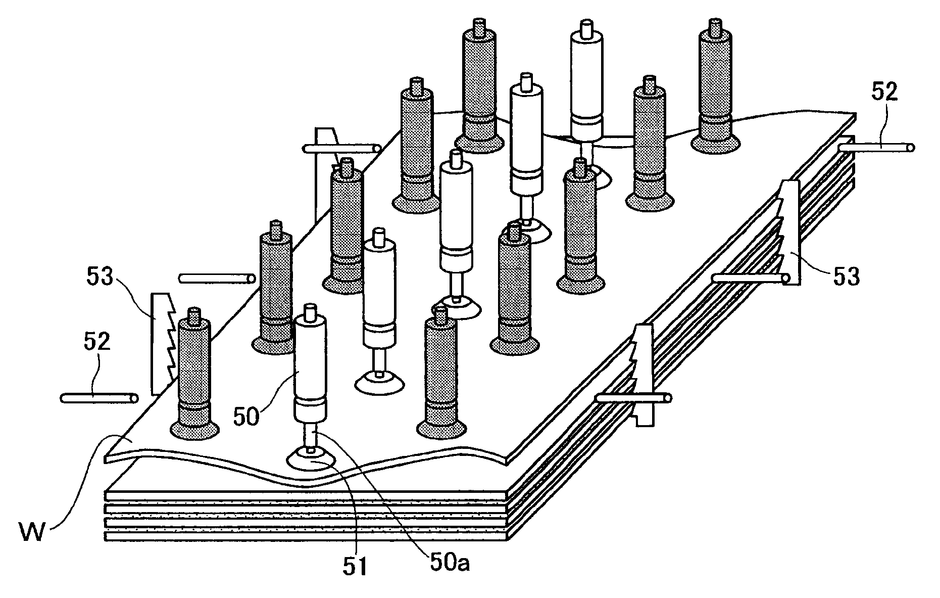
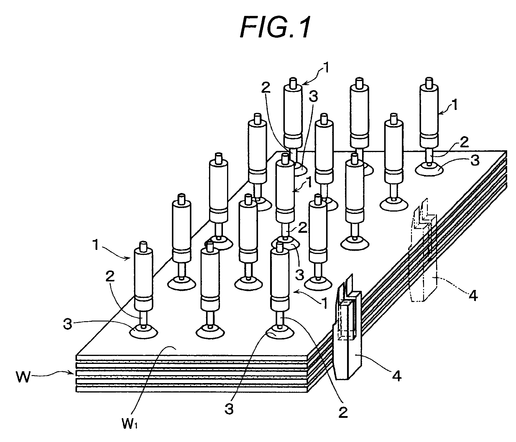
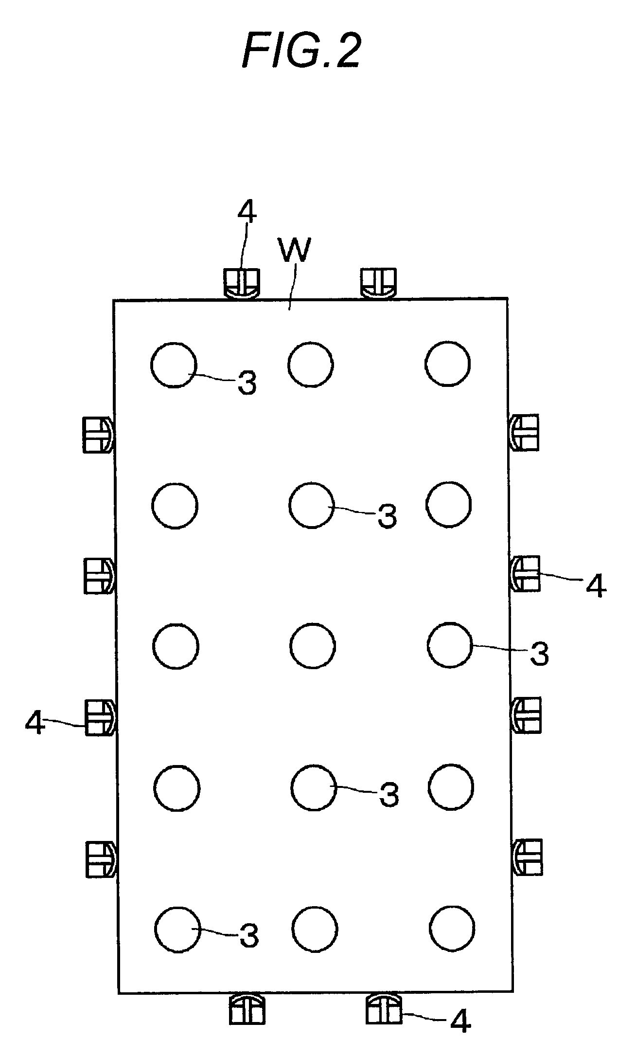
[0063]As the plate member W, there is used an aluminum alloy plate having a size of 1000×1700 mm, a thickness of 1 mm coated with a lubricant for pressing. Further, the work is provided with the first and the second inclined faces 7, 8 at an end portion thereof. 15 pieces of the suction pads 3 are arranged to be adsorbed to a surface of the plate member W in vertical 5 rows and horizontal 3 rows at equal intervals of 30 mm. A diameter of the suction pad 3 is 100 mm, and the stroke L of the air cylinder 1 is 30 through 50 mm. The second and third steps are carried out while blowing out warm wind at 30 through 100° C. from the pipe 4.

[0064]In an experiment of 150 sheets of the plate members W, a rate of capable of separating the plate members W completely is 97.3%. Although 2 sheets are taken in remaining 2.7%, the plate members W are separated when the air cylinder 1 reaches an upper dead point at the third step.

[0065]As a comparative example, an experiment is carried out with regard...


PUM

PropertyMeasurementUnit
temperatureaaaaaaaaaa
angle of inclinationaaaaaaaaaa

Abstract

A method which is capable of completely separating a plate member with a large area without using a peeling member and eliminating a possibility of permanent deformation on the plate member. A plurality of suction pads are suckingly disposed on a surface of a topmost plate member in a substantially lattice shape. Then, while the topmost plate member is held by the suction pads disposed in a zigzag shape among the suction pads disposed in the substantially lattice shape, the topmost plate member is lifted by the remaining suction pads. Finally, the suction pads holding the topmost plate member are lifted.

Description

TECHNICAL FIELD[0001]The present invention relates to a method of separating a topmost plate member from laminated plate members.BACKGROUND ART[0002]In pressing process, a topmost plate member is separated from laminated plate members to be supplied to a press forming machine. It is general to separate the plate members by lifting the topmost plate member by a suction pad. However, the laminated plate members are coated with an oil lubricant having a high viscosity, a rust preventing oil, or the like and are brought into close contact with each other by their own weight. Therefore, it is difficult to completely separate the plate members by such a method and there is a case of simultaneously lifting up a plurality of sheets of plate members. When the plurality of sheets of plate members are taken, the plurality of sheets of plate members are simultaneously supplied to the press forming machine and destroying a die is a concern.[0003]Hence, a method of separating plate members as sho...

Claims


Application Information

Patent Timeline
Patent Type & Authority Patents(United States)
IPC IPC(8): B65H3/30
CPCB65G59/045B65H3/0816B65H3/54B65H3/48B65H2701/18264B65H2301/5121
Inventor MARUYAMA, MANABUNAKAGAWA, YOSHIAKINAKAO, KEIICHIRO
Owner HONDA MOTOR CO LTD
Why Eureka
Try Eureka