Spinal implant installation device

a technology for installing devices and spinal implants, which is applied in the field of spinal implant installation devices, can solve the problems of affecting the delicate nervous tissue proximate the spine, patient may experience symptoms ranging from discomfort to paralysis, and achieve the effect of better accommodating the lateral approach

Active Publication Date: 2013-01-01
NUVASIVE
View PDF22 Cites 28 Cited by
  • Summary
  • Abstract
  • Description
  • Claims
  • Application Information

AI Technical Summary

Benefits of technology

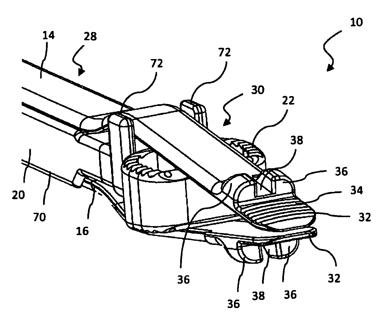
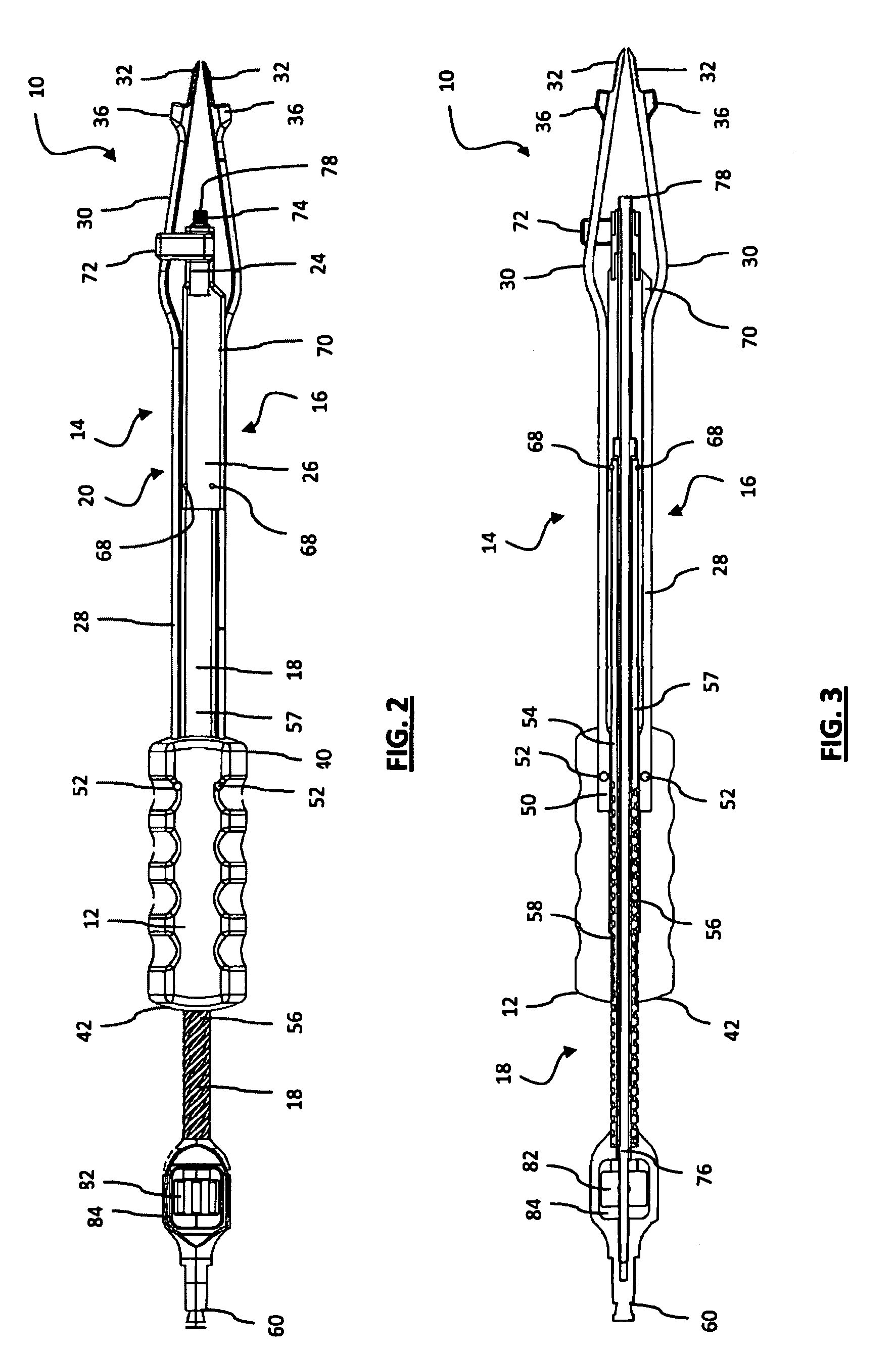
[0020]The non-parallel region of the arms may be longer than that of the device to better accommodate the lateral approach. Rather than extending outward first and then converging together sharply to create space for the implant in the relatively short non-parallel region of the installation device, the non-parallel region of installation device is extended and the arms converge towards each other directly. This creates a sleeker profile and allows the installation device to be advanced through smaller corridors (such as for example, retraction and / or distraction assemblies used to access the lateral aspect of the spine).

Problems solved by technology

If the normal physiology of the spine is disrupted due to trauma, degeneration, or other ailments, the delicate nervous tissue proximate the spine may be affected and the patient may experience symptoms ranging from discomfort to paralysis.

Method used


Image

  • Spinal implant installation device
  • Spinal implant installation device
  • Spinal implant installation device

Examples


Embodiment Construction

[0032]Illustrative embodiments of the invention are described below for the purposes of understanding the principles of the invention. No limitation of the scope of the invention is therefore intended. In the interest of clarity, not all features of an actual implementation are described in this specification. It will of course be appreciated that in the development of any such actual embodiment, numerous implementation-specific decisions must be made to achieve the developers' specific goals, such as compliance with system-related and business-related constraints, which will vary from one implementation to another. Moreover, it will be appreciated that such a development effort might be complex and time-consuming, but would nevertheless be a routine undertaking for those of ordinary skill in the art having the benefit of this disclosure. The device disclosed herein boasts a variety of inventive features and components that warrant patent protection, both individually and in combina...


PUM


Abstract

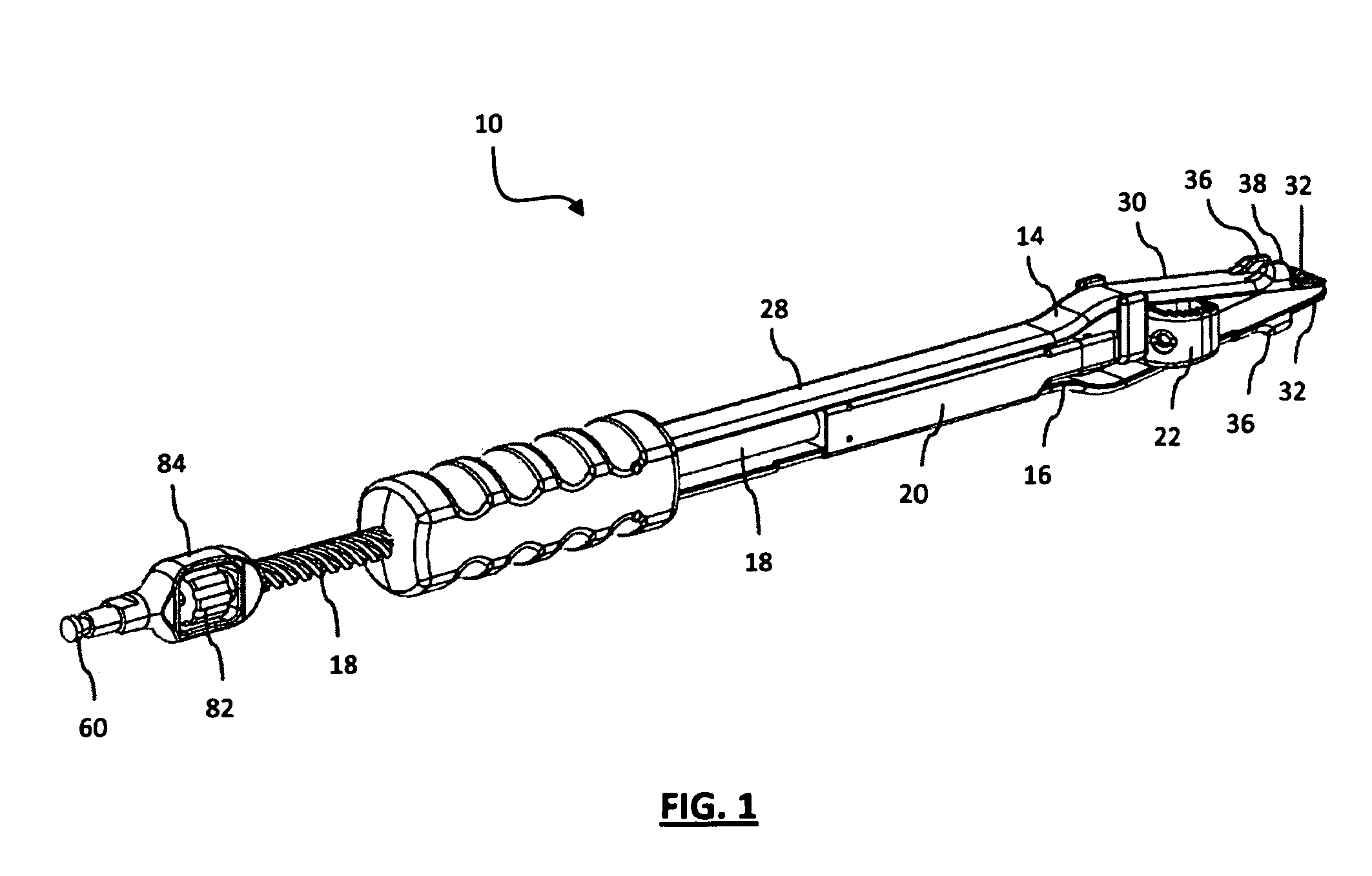
An implant installation device is provided for delivering an implant to a target implantation site including a handle with a first and second arms extending distally therefrom. A translation member extends through the handle such that a distal portion lies between the first arm and second arm while a proximal portion extends beyond the proximal end of the handle. An inserter is coupled at the distal end of the translation member and also lies between the first arm and second arm. With an implant positioned proximate the distal end of the inserter, the distal ends of the arms may be inserted between the pair of vertebrae. The translation member may be operated to drive the inserter distally, which in turn pushes the implant toward the implantation site.

Description

CROSS REFERENCES TO RELATED APPLICATIONS[0001]The present application is a nonprovisional patent application claiming benefit under 35 U.S.C. §119(e) from commonly owned and U.S. Provisional Application Ser. No. 61 / 028,886, entitled “Spinal Distraction and Implantation Assembly and Related Methods,” filed on Feb. 15, 2008, and commonly owned and U.S. Provisional Application Ser. No. 61 / 105,384, entitled “Spinal Distraction and Implantation Assembly & Related Methods,” filed on Oct. 14, 2008, the entire contents of which are each hereby expressly incorporated by reference into this disclosure as if set forth fully herein.BACKGROUND OF THE INVENTION[0002]I. Field of the Invention[0003]The present invention relates generally to delivering and implanting spinal implants during surgery.[0004]II. Discussion of the Prior Art[0005]The spine is formed by a column of vertebra that extends between the cranium and pelvis and includes three major regions known as the cervical, thoracic and lumba...

Claims


Application Information

Patent Timeline
Patent Type & Authority Patents(United States)
IPC IPC(8): A61B17/58
CPCA61F2/4611A61F2/4465A61F2002/4624A61F2002/4627A61F2002/4629A61B2017/0256A61F2/4603
Inventor ARAMBULA, JAREDVERHAGE, BENJAMINLOVELL, NATHAN
Owner NUVASIVE
Why Eureka
Try Eureka