
Integrated building production information system

Inactive Publication Date: 2006-10-31
KAJIMA CORP
View PDF8 Cites 29 Cited by
  • Summary
  • Abstract
  • Description
  • Claims
  • Application Information

AI Technical Summary

Benefits of technology

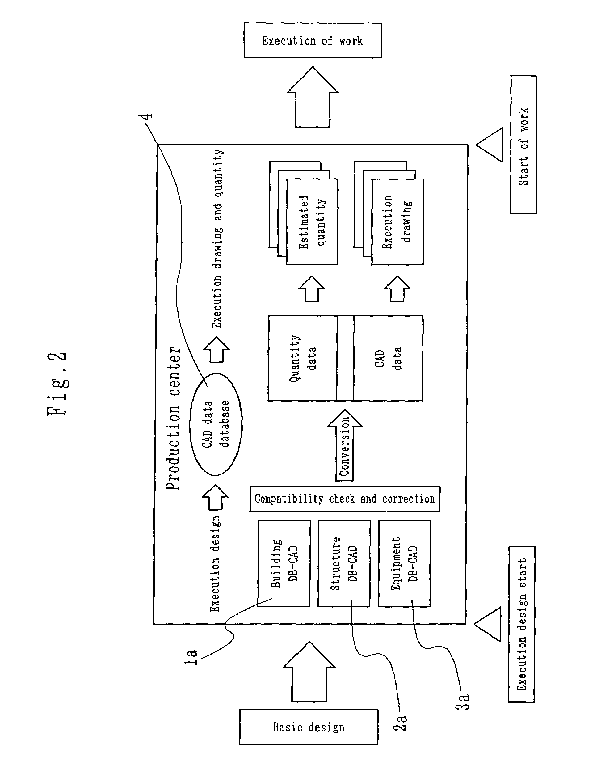
[0036]The present invention aims at solving said disadvantages of the prior art, and a first object of the invention is to realize improving the quality of a design drawing and provide an integrated building production information system in which information is unified by developing a function of linking CAD information and high-quality data being excellent in compatibility made at an execution design stage can be obtained as a result that the compatibility can be spontaneously obtained or that the efficiency of collation work can be improved.
[0037]A second object of the invention is to shorten the whole process and provide an integrated building production information system in which a work of making data compatible can be easily advanced further in a short time, and, therefore, the whole process is shortened and furthermore, the compatible data can be diverted and utilized at the estimation and execution stages after the execution design stage and the efficiency of building production can be comprehensively improved.

Problems solved by technology

However, for all CAD data of drawings made with much effort, there has not been a mechanism for utilizing them in a process of estimating quantities or preparing execution drawings being the next process.
On the other hand, execution design drawings and specifications representing the contents of estimation and contract have contained a too small amount of information and a too large amount of pending contents to perform execution as they are.
Such present situation has hindered the rationalization in various aspects.
Securing the compatibility at an execution stage results in having many pending matters, and redo and readjustment occur even in the course of execution as described above and the rationalization is hindered in various aspects by entering the next process as leaving necessary information not definitely determined.
And this system uses pattern data of a drawing but does not inheritably use the attribute of a design drawing.
The linkage of such pattern data is low in the degree of freedom and the CAD data of a design drawing can be utilized in making a synthetic drawing in the next process as pattern data, but since the attribute of it is not utilized, the data cannot be utilized in calculation of quantities to be estimated.
Hei 8-235,243 is a system which fully performs a layer management of drawing data and converts the layer of drawing data into a layer configuration convenient for a synthetic drawing on the basis of a predetermined rule of layer conversion, but the layer rule is not often strictly observed and an effective result cannot be often obtained.
Generally, management based on layer is effective for an object but is often ineffective for another object, and in case of using a layer management for another object, such a system performs conversion but often cannot effectively distribute data.
Hei 8-235,243 is supposed as a system primarily handling two-dimensional matters and cannot perform examination from an optional direction in confirming the compatibility and is difficult to estimate exactly the quantities.
There are such reasons as a fact that a CAD system has been expensive in lease expense of hardware / software, maintenance cost and the like, a fact that there has not been a receiver of data since CAD has not been popular in building sites, a fact that estimation is often performed by manually picking up and no electronic data have been utilized in a downstream process, and a fact that an operator has been required not only to operate a CAD system but also to have deep knowledge of both design drawings and execution drawings, namely, a young operator skilled in operation of CAD has also needed to be skilled in settlement or sequence of execution and the like.
And two-dimensional data are primarily handled and the correction of errors caused by conversion requires much time, and it is difficult to check the compatibility by means of two-dimensional superposition of pattern data.

Method used


Image

  • Integrated building production information system
  • Integrated building production information system
  • Integrated building production information system

Examples


Embodiment Construction

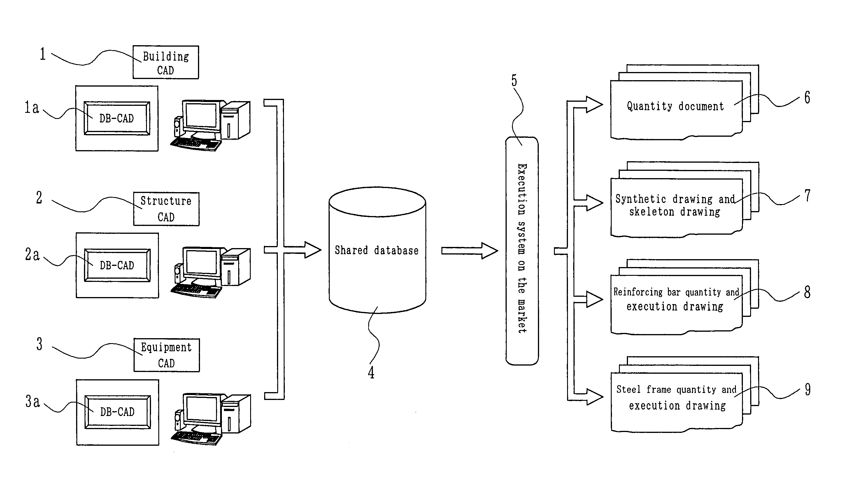
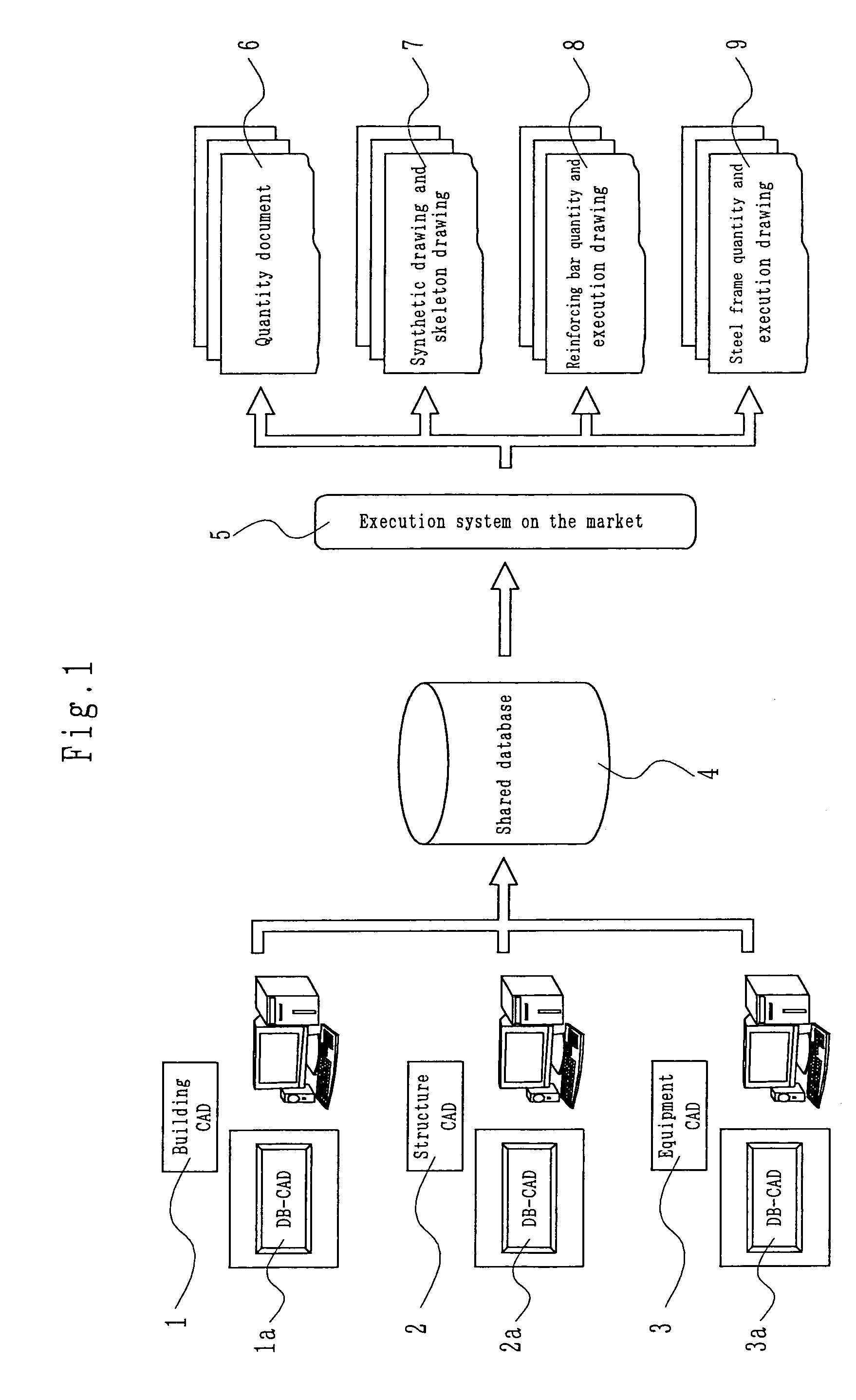
[0090]An embodiment of the present invention is described in detail with reference to the drawings in the following. FIG. 1 is an explanatory diagram showing an embodiment of an integrated building production information system of the present invention, and numbers 1, 2 and 3 in this figure are respectively a building CAD, a structure CAD and an equipment CAD as design CAD's, and are based on different software products according to their respective features.

[0091]There are provided databases DB-CAD (building) 1a, DB-CAD (structure) 2a and DB-CAD (equipment) 3a built in the outside separately from these design CAD's including building CAD 1, structure CAD 2 and equipment CAD 3.

[0092]Taking building CAD 1 and DB-CAD (building) 1a as an example, the exchange of data between a CAD and an external DB is ordinarily performed as text data obtained by being converted into the CSV (comma separated value) format, and an interface making it possible to directly write / read from building CAD 1 ...


PUM


Abstract

An integrated building production information system including design CAD (computer-aided-design) based on software of building, structure, and equipment, and databases built in the outside separately from the design CAD, the databases making an integrated DB (shared database)-CAD system of building, structure and equipment as an execution-linked system in DB-CAD's sharing of a standard database, wherein the integrated building production information system stores the information made compatible by three-dimensional superposition at the time of design into a shared database (DB) of the integrated DB-CAD system, and further receives and links information of this shared database to extemal systems such as a skeleton drawing CAD, a reinforcing bar and steel frame system and the like and produces execution information.

Description

BACKGROUND OF THE INVENTION[0001]1. Technical Field of the Invention[0002]The present invention relates to an integrated building production information system capable of making the work solution of a design department and an execution department more rational and more efficient by electronicizing key jobs (integration, estimation, procurement, profit-and-loss management and the like) of the production side in a field of construction.[0003]2. Background Art[0004]Particularly, the present invention relates to a database CAD (computer-aided design) system which can aim at making more efficient and more laborsaving the work of preparing design drawings and specifications and at improving the productivity and quality by making it possible for personal computers using CAD software connected with a database to grasp necessary quantities and share necessary data for design among the personal computers, by integrating specifications and quantities in a design work using CAD's performed by e...

Claims


Application Information

Patent Timeline
IPC IPC(8): G06F17/50
CPCG06F17/5004Y10S707/99953Y10S707/99956Y10S715/964G06F30/13
Inventor TAKAGAKI, TOHRUTANAKA, SHUNSUKETAMAI, HIROSHIYASUZAWA, TAKEROUYASAKA, AYAKOTSUJIMOTO, MINORUENDOU, YUKIOTANI, YASUFUMISANO, YUKIOTAKAGI, MANABUTAKAHASHI, TAKETOSHIUENO, SHIGEHIKOUENAMI, TETUROUWAKASUGI, KAZUO
Owner KAJIMA CORP
Learn More