
Process of forming a microperforated polymeric film for sound absorption

a technology of micro-perforation and polymeric films, applied in the field of sound absorption, can solve the problems of fiber-based sound absorbers with significant inherent disadvantages, degrade the air quality of the surrounding environment, and require expensive treatment, etc., and achieve the effect of uniform thickness of the film

Inactive Publication Date: 2010-06-08
3M INNOVATIVE PROPERTIES CO
View PDF101 Cites 39 Cited by
  • Summary
  • Abstract
  • Description
  • Claims
  • Application Information

AI Technical Summary

Problems solved by technology

Despite their advantages in broad-band absorption, fiber-based sound absorbers have significant inherent disadvantages.
Such sound absorbers can readily release particulate matter and deleteriously degrade the air quality of the surrounding environment.
Some fiber-based sound absorbers are also sensitive to heat or fire and / or require expensive treatment to provide heat / fire resistance.
Consequently, fiber-based sound absorbers are of limited use in many environments.
While these perforated sheet-based sound absorbers may overcome some of the inherent disadvantages of fiber-based sound absorbers, they are expensive and / or of limited use in many applications.
For instance, the use of very thick and / or very stiff materials or use of thickening strips or external support for the perforated sheets limits the use of sound absorbers using such sheets.
The necessary thickness / stiffness or strips / external support also makes the perforated sheets expensive to manufacture.
Finally, the perforated sheets must be provided with expensive narrow diameter perforations or else used in limited situations involving tonal sound.
However, the punching, stamping or laser drilling techniques used to form such small hole diameters are very expensive.

Method used


Image

  • Process of forming a microperforated polymeric film for sound absorption
  • Process of forming a microperforated polymeric film for sound absorption
  • Process of forming a microperforated polymeric film for sound absorption

Examples


Embodiment Construction

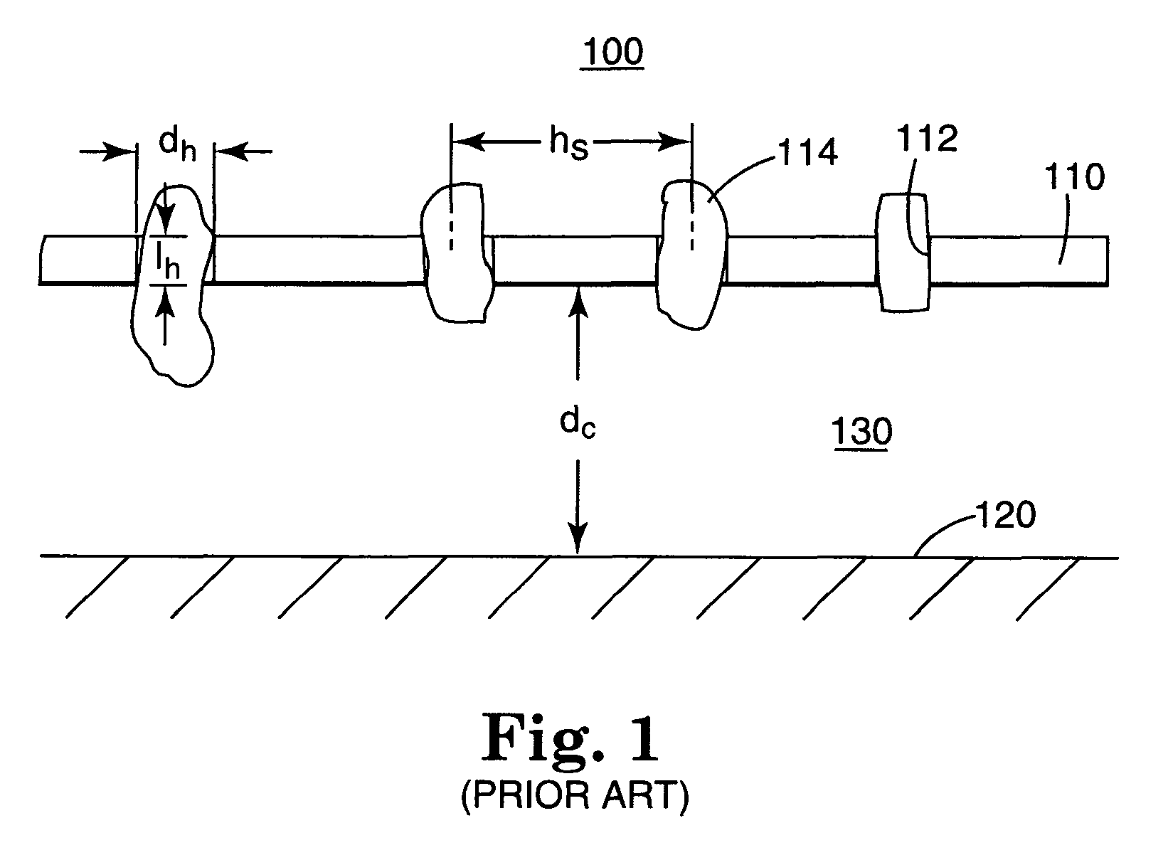
[0031]FIG. 1 schematically illustrates a perforated sheet-based sound absorber. The sound absorber 100 generally includes a perforated sheet 110 disposed near a reflecting surface 120 to define a cavity 130 therebetween. The perforated sheet 110 generally includes a plurality of perforations or holes 112 having a diameter dh and a length lh corresponding to the thickness of the sheet 110. As will be explained below, the hole diameter dh and length lh as well as the depth of the cavity dc and the spacing hs of the holes 112 have a significant impact on the sound absorption capabilities of the sound absorber 100. Conceptually, the sound absorber 100 may be visualized as a resonating system which includes, as a mass component, plugs 114 of air which vibrate back and forth in the holes 112 and, as a spring component, the stiffness of the air in the cavity 130. In response to incident sound waves, the air plugs 114 vibrate, thereby dissipating sound energy via friction between the moving...


PUM

PropertyMeasurementUnit
hole diametersaaaaaaaaaa
aperture diametersaaaaaaaaaa
narrowest diameteraaaaaaaaaa

Abstract

A process of forming a microperforated plastic film includes providing a post tool having multiple posts, bringing plastic into contact with the post tool such that the plastic conforms to the shape of the posts, and solidifying the plastic into a solidified plastic film having a plurality of microperforations in the shape of the posts. Another step in the process is displacing any skins formed over the holes after solidifying the plastic. The process may be used to form a film for sound absorption where the posts are shaped and arranged to provide microperforations that provide a particular sound absorption spectrum. In one embodiment, the microperforations each have a narrowest diameter of 20 mils, a narrowest diameter less than a film thickness, and a widest diameter greater than narrowest diameter. The widest diameter may be about 125% or more of the narrowest diameter in an embodiment.

Description

CROSS REFERENCE TO RELATED APPLICATIONS[0001]This application is a divisional of U.S. application Ser. No. 09 / 537,243, filed Mar. 28, 2000, now issued as U.S. Pat. No. 6,977,109; which is a divisional of U.S. application Ser. No. 09 / 122,240, filed Jul. 24, 1998, now issued as U.S. Pat. No. 6,617,002, the disclosure of which is herein incorporated by reference.FIELD OF THE INVENTION[0002]The present invention generally relates to sound absorption and, more particularly, to microperforated polymeric films for sound absorption and sound absorbers using such films.BACKGROUND OF THE INVENTION[0003]Sound absorbers have been widely used in a number of different disciplines for absorbing sound. The most common sound absorbers are fiber-based and use fibrous materials such as fiberglass, open-cell polymeric foams, fibrous spray-on materials often derived from polyurethanes, and acoustic tile (an agglomerate of fibrous and / or particulate materials). Such fibrous-based sound absorbers rely on ...

Claims


Application Information

Patent Timeline
Patent Type & Authority Patents(United States)
IPC IPC(8): B29C47/00G10K11/16
CPCG10K11/16Y10S425/037Y10S264/70Y10T428/24273
Inventor WOOD, KENNETH BRIAN
Owner 3M INNOVATIVE PROPERTIES CO
Learn More