Pipette

a pipette and pipette technology, applied in the field of pipette, can solve problems such as the displacement of the transfer element, and achieve the effect of saving forces and low friction

Active Publication Date: 2010-06-08
EPPENDORF SE
View PDF8 Cites 44 Cited by
  • Summary
  • Abstract
  • Description
  • Claims
  • Application Information

AI Technical Summary

Benefits of technology

[0009]The inventive pipette has the advantage that it is possible to separate a syringe from the pipette by actuating a single, central trigger. Indeed, an actuation of the trigger results in a displacement of the transfer element coupled thereto within the guide. Here, the transfer element hits the abutment area onto the release levers, pivoting them and the syringe gripping levers as well. As a consequence, the syringe gripping levers liberate the mounting portion of the syringe. At this stage, the syringe gripping levers are pivoted against the actuator arms of the piston gripping levers, causing them to let the syringe piston go at a slight time lag. Thus, an actuation of a single trigger causes a separation of the syringe from the pipette. This maintains the beneficial axial connectability of the syringe to the pipette. If the pipette is designed in an appropriate way such axial connectability can be brought about by merely fitting the pipette onto the mounting portion and syringe piston of the syringe.
[0013]According to an aspect, the transfer element is joined to a trigger laterally projecting from the pipette casing transversely to the guide. The trigger can be conveniently actuated without gripping around it by the thumb which also actuates the repeat mechanism, specifically when the trigger is disposed close to that end of the pipette casing which faces away from the seat.
[0014]According to an aspect, the trigger is disposed in the vicinity of that end of the pipette casing which is remote from the seat. This makes it easier to operate the trigger.
[0018]According to an aspect, the release levers exhibit rounded corners. The rounded corners are capable of rolling down on the abutment area of the transfer element at a low friction and, thus, will save forces.

Problems solved by technology

Indeed, an actuation of the trigger results in a displacement of the transfer element coupled thereto within the guide.

Method used


Image

  • Pipette
  • Pipette

Examples


Embodiment Construction

[0029]While this invention may be embodied in many different forms, there are described in detail herein a specific preferred embodiment of the invention. This description is an exemplification of the principles of the invention and is not intended to limit the invention to the particular embodiment illustrated

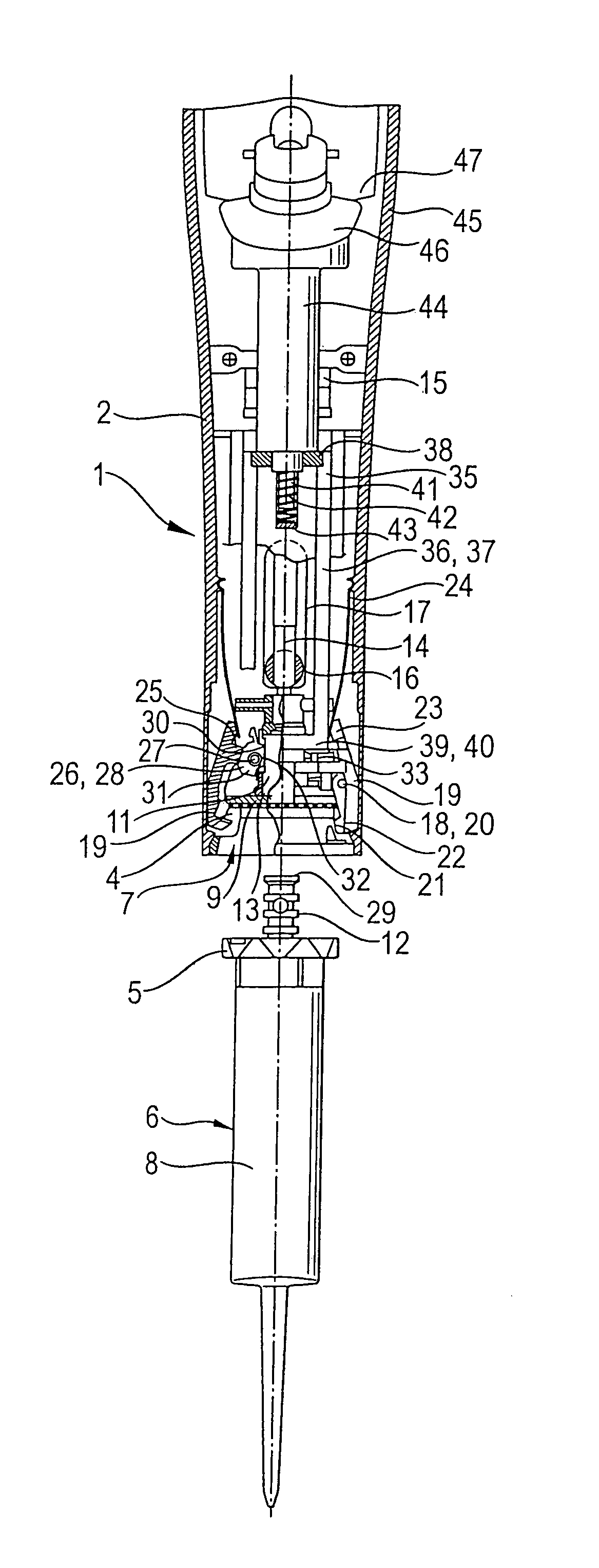
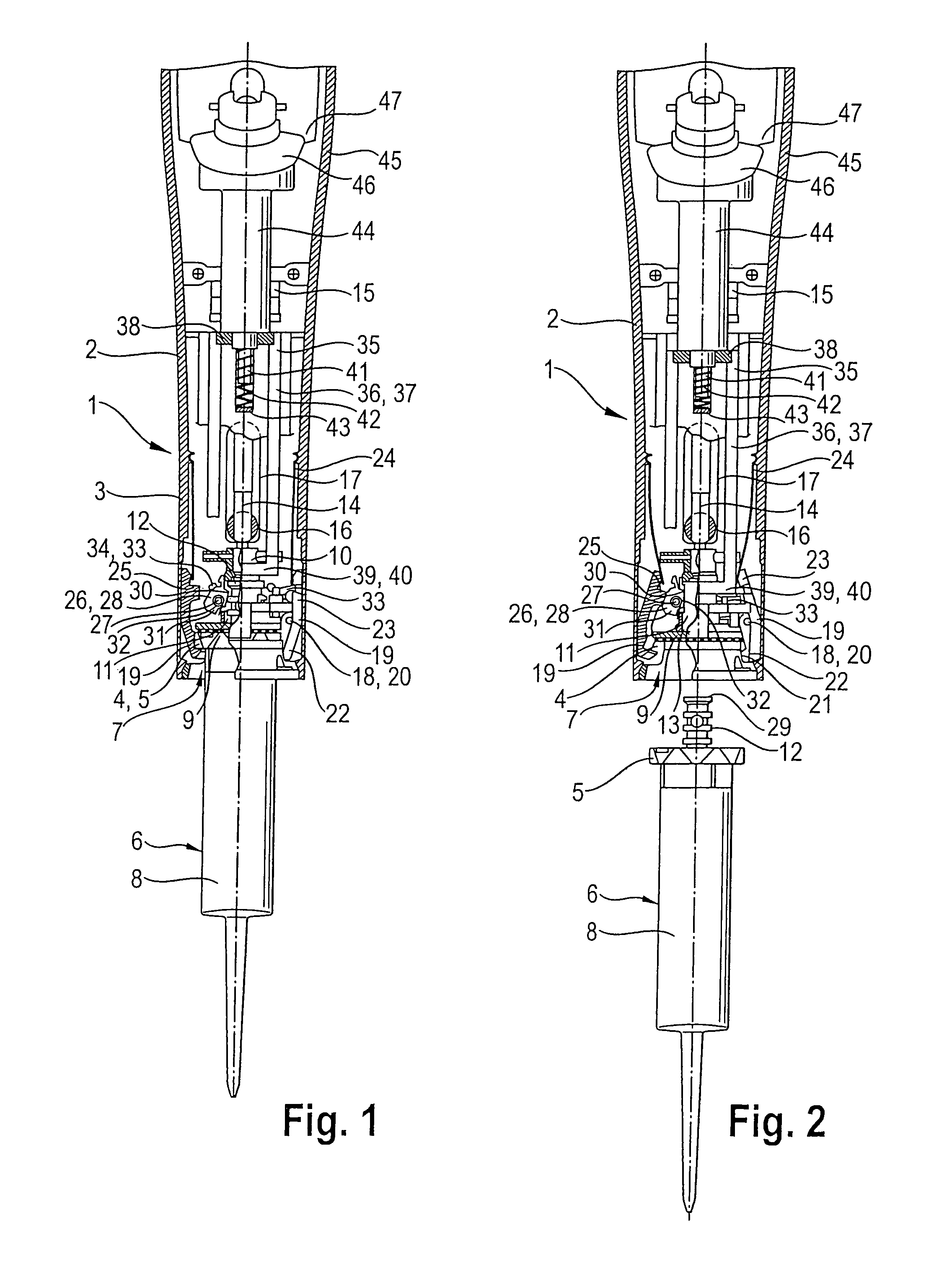
[0030]The terms “bottom”, “below”, and “top”, “above” hereinafter will refer to the orientation of the pipette when used with the syringe held downwards.

[0031]The pipette 1 has a pipette casing 2 with a substantially cylindrical casing bottom 3. The lower end portion of the casing bottom 3 has disposed therein a seat 4 for a syringe flange 5 of a syringe 6. The syringe flange 5 is a mounting portion of the syringe 6. At the lower end of the casing bottom 3, the seat 4 has an axial aperture 7 through which the syringe 6 retained in the seat 4 makes protrude its syringe cylinder 8.

[0032]The seat 4 has disposed therein a spring-loaded abutment 9 against which the upper side of th...


PUM


Abstract

A pipette, comprising a pipette casing which has disposed therein a seat, a piston seat in an accommodating body, mounting devices for reversibly fixing the mounting portion and syringe piston of a syringe within the seats and piston adjusting devices for displacing the accommodating body, wherein the mounting portion and syringe piston are adapted to be slid to their mounting positions through axial apertures, the mounting devices have radially advanceable gripping devices, the gripping devices have syringe gripping levers pivotally supported within the pipette casing and piston gripping levers pivotally supported within the accommodating body, the syringe gripping levers and piston gripping levers have two arms, the syringe gripping levers, at the insides of their actuator arms, having contact points which when their actuator arms are actuated are adapted to be externally pivoted against the actuator arms of the piston gripping levers, the syringe gripping levers have inwardly projecting release levers on the actuator arms, a transfer element which is slidably guided transversely with respect to the release levers within the pipette casing is adapted to be brought into abutment against the two release levers by being shifted by a front-end sided abutment area, and a trigger displaceable within the pipette casing is coupled to the transfer element to displace the transfer element upon displacement of the trigger.

Description

CROSS-REFERENCE TO RELATED APPLICATIONS[0001]Not applicable.STATEMENT REGARDING FEDERALLY SPONSORED RESEARCH[0002]Not applicable.BACKGROUND OF THE INVENTION[0003]The invention relates to a pipette.[0004]Pipettes are devices for metering and transferring liquids. They frequently are configured as repeat pipettes or multi-pipettes which allow to dispense a liquid from a syringe in a stepwise manner. A repeat pipette of this type has been known from DE 29 26 691 C2, which is specifically directed to the repeat mechanism of the repeat pipette. The document also describes how to fix a syringe of the system to the repeat pipettes. For this purpose, the syringe has a syringe flange which is adapted to be introduced from a side into a groove which is open laterally and substantially is U-shaped. The syringe flange inserted is fixed in the groove by an axial pressure spring. An insertion element is provided to join the syringe piston to a piston adjusting device and accommodates an end porti...

Claims


Application Information

Patent Timeline
Patent Type & Authority Patents(United States)
IPC IPC(8): B01L3/02
CPCB01L3/0279B01L3/0234B01L2300/021
Inventor LENZ, JURGEN
Owner EPPENDORF SE
Why Eureka
Try Eureka