Rechargeable battery

a rechargeable battery technology, applied in the field of rechargeable batteries, can solve the problems of weak bond between the protective circuit board and the bare cell, and achieve the effect of stable and simple manner

Inactive Publication Date: 2010-06-08
SAMSUNG SDI CO LTD
View PDF6 Cites 3 Cited by
  • Summary
  • Abstract
  • Description
  • Claims
  • Application Information

AI Technical Summary

Benefits of technology

[0024]The present invention solves the above-mentioned problems occurring in the prior art. Accordingly, an object of the present invention is to provide a rechargeable battery formed in such a manner that a bare cell can be coupled with a safety device such as a protective circuit board, in a stable and simple manner.
[0025]It is another object of the present invention to provide a rechargeable battery formed in such a manner that the problems of conventional pack-type batteries can be avoided. Such problems include that complicated plastic molding process is used, the gap between the protective circuit board and the bare cell is not uniformly filled with a resin for plastic molding, and the bond between the protective circuit board and the bare cell is weak.
[0026]It is still another object of the present invention to provide a rechargeable battery assembled in such a manner that a safety device attached to a bare cell can be recycled and reused, even if the bare cell is discarded.
[0028]According to the present invention, the bonding surface of the battery component part including the safety device such as a protective circuit board and the bonding surface of the bare cell generally have electric terminals or electric connections. To simplify the structure of a rechargeable battery, it is preferable that at least a part of the bonding part functions not only as a mechanical bonding part between the bare cell and the safety device, but also as an electric terminal for making an electric connection.

Problems solved by technology

Such problems include that complicated plastic molding process is used, the gap between the protective circuit board and the bare cell is not uniformly filled with a resin for plastic molding, and the bond between the protective circuit board and the bare cell is weak.

Method used


Image

  • Rechargeable battery
  • Rechargeable battery
  • Rechargeable battery

Examples


Embodiment Construction

[0035]Hereinafter, a preferred embodiment of the present invention will be described with reference to the accompanying drawings. In the following description and drawings, the same reference numerals are used to designate the same or similar components, and so repetition of the description on the same or similar components will be omitted.

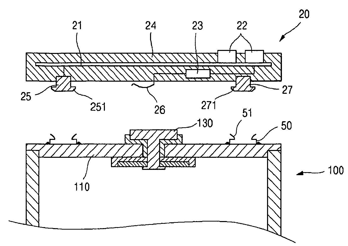
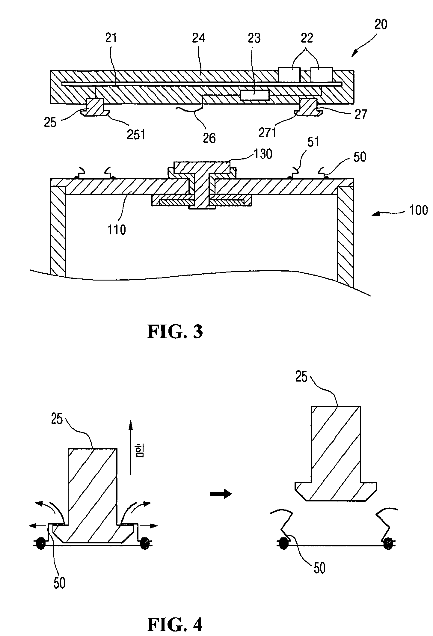
[0036]FIGS. 3 and 5 are schematic sectional views showing the structure of a battery component part and the upper part of a bare cell according to preferred embodiments of the present invention; and FIG. 4 is an illustrative view showing how to separate a coupled structure of a battery component part and a bare cell in the embodiment as shown in FIG. 3.

[0037]Referring to FIG. 3, a rechargeable battery includes a battery component part 20 and a bare cell 100. The battery component part 20 includes a protective circuit board 21 and a bimetal device 23 that are connected to each other in series through electric terminals, the protective circuit board...


PUM

PropertyMeasurementUnit
sizeaaaaaaaaaa
mechanicalaaaaaaaaaa
mechanical bondingaaaaaaaaaa

Abstract

Disclosed is a rechargeable battery including: a bare cell composed of an electrode assembly including a negative electrode, a separator and a positive electrode, a container for housing the electrode assembly and an electrolyte, and a cap assembly for closing an opening of the container; and a safety device electrically coupled to an outer surface of the bare cell, wherein the safety device is coupled to the bare cell by being incorporated into a battery component part, and each of bonding surfaces of the bare cell and the battery component to be bonded to each other has a bonding parts capable of forming a mechanical bonding between the bare cell and the battery component. The rechargeable battery permits a safety device such as a protective circuit board and a bimetal device to be coupled to a bare cell in a stable and simple manner. Additionally, the mechanical bonding parts between the safety device and the bare cell can be separated so that the safety device such as a protective circuit board can be reused.

Description

CROSS REFERENCE TO RELATED APPLICATION[0001]This application claims priority to and the benefit of Korean Patent Application No. 2004-0002442, filed on Jan. 13, 2004, which is hereby incorporated by reference for all purposes as if fully set forth herein.BACKGROUND OF THE INVENTION[0002]1. Field of the Invention[0003]The present invention relates to a rechargeable battery, and more particularly to a rechargeable battery including a bare cell having an electrode assembly, a can and a cap assembly, and a protective circuit board electrically and mechanically connected to the bare cell.[0004]2. Description of the Prior Art[0005]As generally known in the art, rechargeable batteries are rechargeable and can be made in a compact form with a large capacity for energy storage, and thus have been broadly researched and developed recently. Typical examples of such rechargeable batteries include nickel-hydrogen (Ni—H) batteries, lithium (Li) batteries and lithium-ion (Li-ion) batteries.[0006]I...

Claims


Application Information

Patent Timeline
Patent Type & Authority Patents(United States)
IPC IPC(8): H01M14/00H01M10/00H01M2/04H01M10/04H01M10/48H01M50/588
CPCH01M2/34H01M2/348H01M10/486H01M10/0436Y10T29/49108Y02E60/10H01M50/581Y02P70/50H01M50/588H01M50/572
Inventor HAN, KYU NAM
Owner SAMSUNG SDI CO LTD
Why Eureka
Try Eureka