Oscillating, deflectable micromechanical element and method for use thereof

a micromechanical element and oscillating technology, applied in the field of micromechanical elements, can solve the problems of further disadvantages, collapse of oscillation, and substantial increase of effort and/or cost for the control of such a deflection, and achieve the effect of increasing sensitivity and widening the useful frequency rang

Active Publication Date: 2011-04-26
FRAUNHOFER GESELLSCHAFT ZUR FOERDERUNG DER ANGEWANDTEN FORSCHUNG EV
View PDF9 Cites 2 Cited by
  • Summary
  • Abstract
  • Description
  • Claims
  • Application Information

AI Technical Summary

Benefits of technology

[0032]Production tolerances which, for example, effect a corresponding natural resonant frequency can be compensated better. This has a particularly advantageous effect with a multidimensional deflection. In this respect, as a rule, specific frequency ratios have to be maintained on the deflection around at least two axes to enable deflections while observing resonant conditions. If, however, as a result of a non-observed production tolerance parameter, at least one mechanical natural resonant frequency differs, such an operation is not possible. This can, however, be compensated with the invention due to the larger useful frequency range.
[0033]If the invention is used with sensitive elements for the detection of physical measurement parameters, their sensitivity can be increased.

Problems solved by technology

In this respect, in addition to a hysteresis effect, further disadvantages also occur.
This substantially increases the effort and / or cost for the control of such a deflection since the oscillation collapses at a frequency below the resonant frequency.
This has the result that with an oscillation with a maximum amplitude of the deflection, every ever so small reduction in the excitation frequency results in the collapse of the oscillation.
A correspondingly high effort and / or cost for the regulation is necessary.
The deflection must therefore be limited to secure a stable operation so that a maximum possible deflection cannot be utilized.
A small change in the excitation frequency in the proximity of the resonant frequency can thus result in an increased rise in the amplitude.
This maximum achievable deflection is in particular limited with a small length and linear spring characteristics of the spring elements used which should be operated at very high frequencies.
In conjunction with the previously described disadvantages and with a non-regulated operation, this has the result that the maximum possible deflection cannot be reached.
The frequency retardation on start-up would have to be reversed from a specific amplitude / frequency ratio onward, which is not possible in reality in a non-regulated operation.

Method used


Image

  • Oscillating, deflectable micromechanical element and method for use thereof
  • Oscillating, deflectable micromechanical element and method for use thereof
  • Oscillating, deflectable micromechanical element and method for use thereof

Examples


Embodiment Construction

[0043]Eight examples for possible embodiments of spring elements usable in the invention are thus shown in FIG. 5. A region aligned in a straight line in the direction of the longitudinal axis is shown in all of them with the exception of the example shown at the right in the lower row. The examples shown in the upper row have a fork / branching at an end face which is made in V shape or also in U shape.

[0044]The examples shown in the lower row have forks / branches at both end faces which can each also have different designs or be changed with respect to their length in the direction of the longitudinal axis.

[0045]The example shown at the far right in the lower row is formed from two forks / branchings directly connected to one another, with one being made in U shape and the other in V shape.

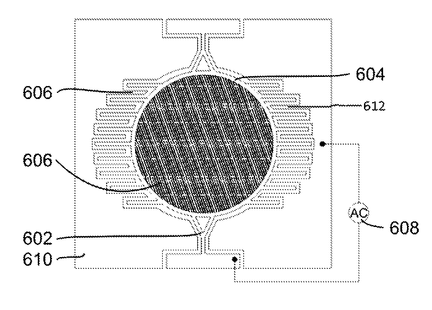
[0046]FIG. 6 shows a schematic diagram 600 of a micromechanical element in accordance with one or more aspects. The micromechanical element can be formed as a comb drive element 604 in accordance wit...


PUM


Abstract

The invention relates to micromechanical elements deflectable in an oscillating manner and to a method for the operation of such elements. In this respect, it is the object of the invention to be able to operate the micromechanical elements in a stable and simple manner on the oscillating deflection while taking account of the respective mechanical resonant frequency. A least one spring element is present on elements in accordance with the invention with which it is held. It is deflected between two reversal points using an electrical AC voltage. The one or more spring element(s) has/have non-linear spring characteristics so that a changed mechanical resonant frequency results in dependence on the respective deflection.

Description

BACKGROUND[0001]The invention relates to micromechanical elements deflectable in an oscillating manner and to a method for the operation of such elements.[0002]Spring-mass oscillators are frequently used as oscillators in micromechanics. In this connection, movably supported elements having mass are held by one or more spring elements. The spring elements effect restoring forces in the direction of the position of rest of the deflected elements. The oscillating deflection between two reversal points can be initiated using electrical AC voltage. In this process, the resonant frequency of an element deflected in an oscillating manner can be taken into account and utilized for a maximum deflection achievable with a reduced performance.[0003]The drive therefore frequently takes place at least in the proximity of a resonant frequency.[0004]This is problematic, for example, with a drive concept which is called an “out-of-plane electrode comb” and is described by H. Schenk in the following...

Claims


Application Information

Patent Timeline
Patent Type & Authority Patents(United States)
IPC IPC(8): H03B5/18H01L27/14
CPCB81B3/0078B81B2203/0109B81B2201/042
Inventor SCHENK, HARALDWOLTER, ALEXANDERSANDNER, THILODRABE, CHRISTIANKLOSE, THOMAS
Owner FRAUNHOFER GESELLSCHAFT ZUR FOERDERUNG DER ANGEWANDTEN FORSCHUNG EV
Why Eureka
Try Eureka