Longitudinal load limiting devices for transmission lines and the like

a technology of longitudinal load limiting and transmission lines, which is applied in the direction of maintaining the distance between parallel conductors, machine supports, other domestic objects, etc., can solve the problems of tower failure, limited use of towers, and cascading failure of many towers

Inactive Publication Date: 2010-06-08
PEABODY ALAN B
View PDF7 Cites 16 Cited by
  • Summary
  • Abstract
  • Description
  • Claims
  • Application Information

AI Technical Summary

Benefits of technology

[0014]Finally, U.S. Pat. No. 3,211,260 teaches an arrester that has a large body of material held in a housing. When excessive force is applie

Problems solved by technology

These events cause large unbalanced longitudinal loads on the tower that can cause tower failure.
One longitudinal tower failure can transfer load to the adjacent tower causing it to also fail leading to a cascading failure of many towers in a particular line.
The problem with these mechanical fuses is that they all have limitations on their use.
They are complicated devices with many parts.
Freezing rain and fog can cause buildups of ice that prevent their pro

Method used


Image

  • Longitudinal load limiting devices for transmission lines and the like
  • Longitudinal load limiting devices for transmission lines and the like
  • Longitudinal load limiting devices for transmission lines and the like

Examples


Embodiment Construction

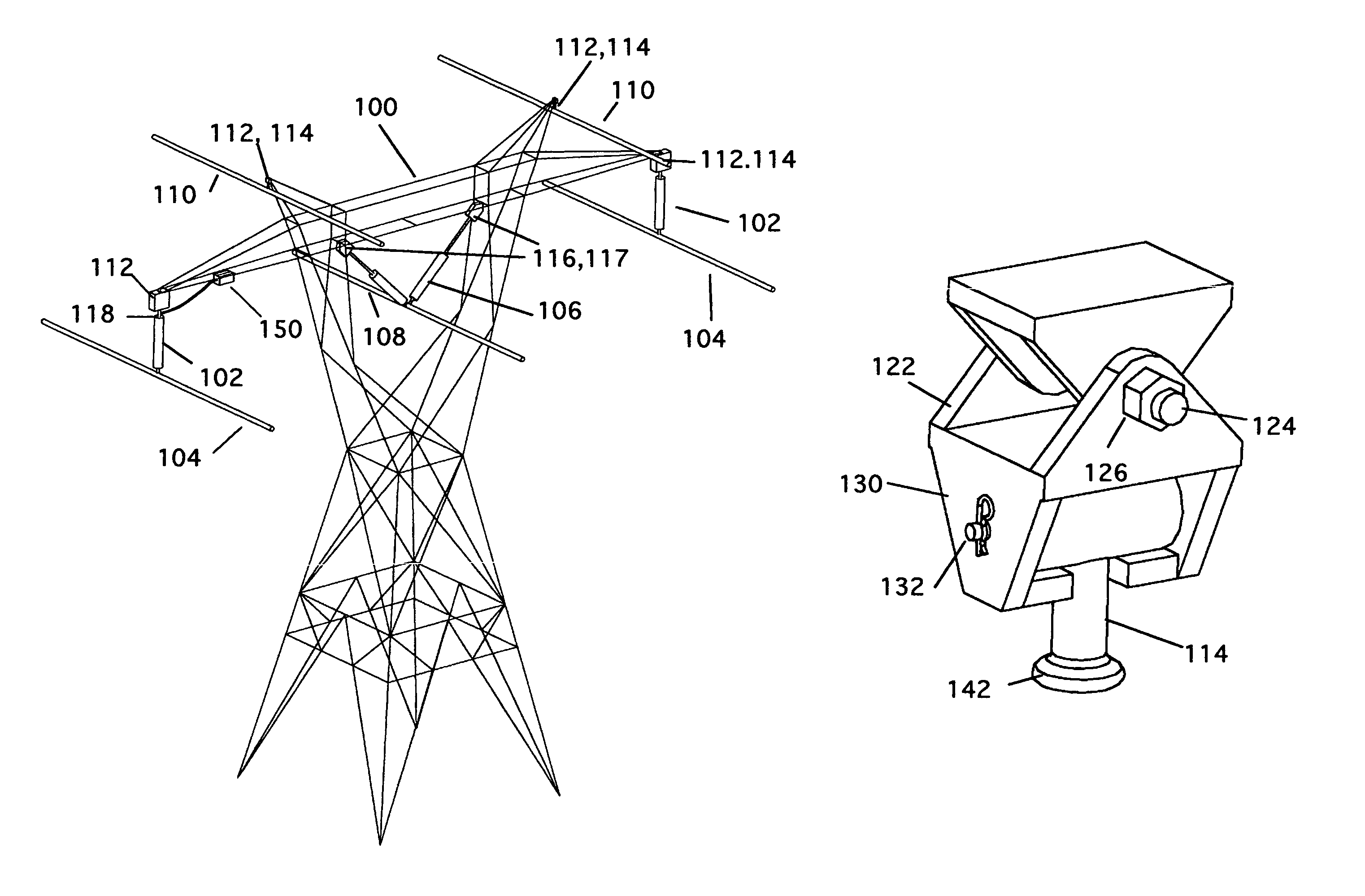
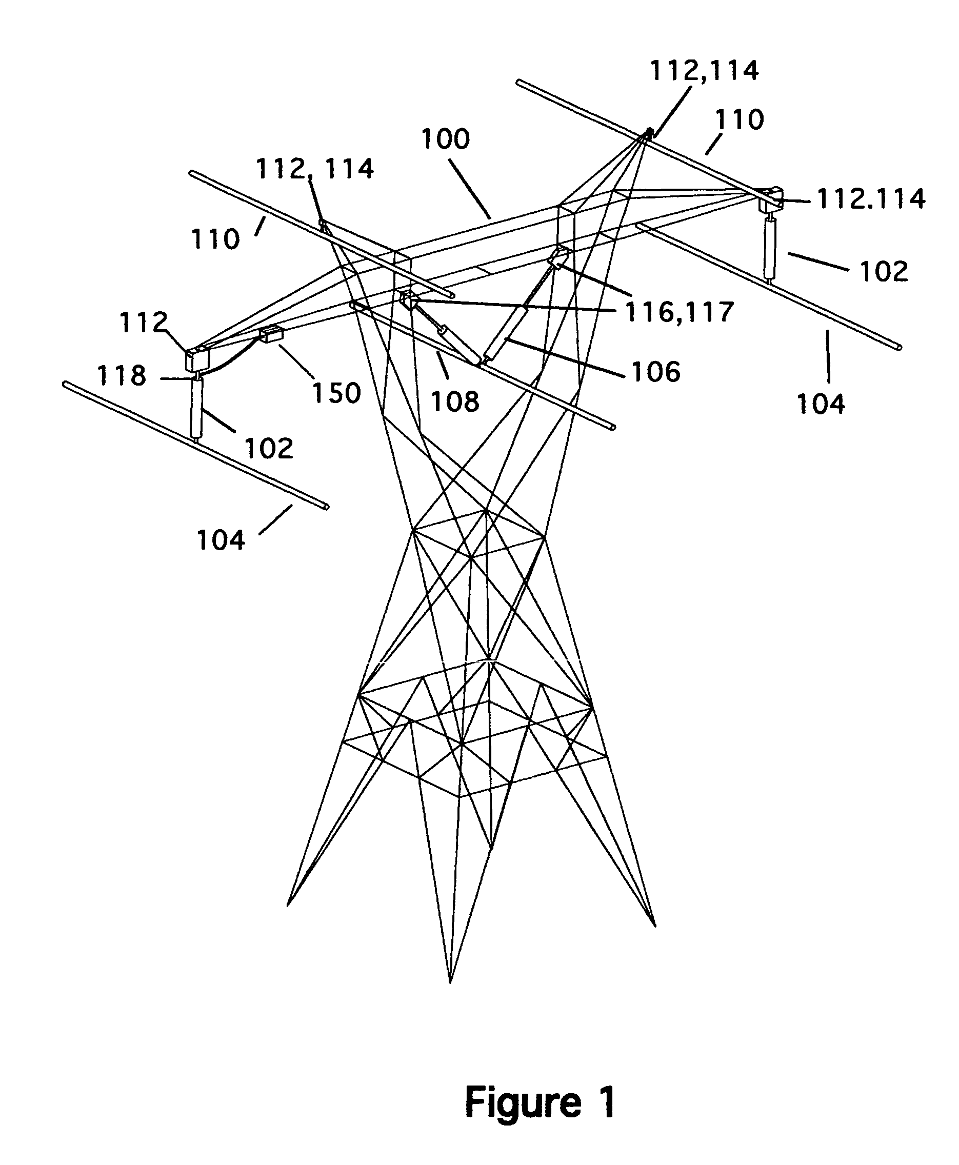
[0037]FIG. 1 shows a typical transmission structure 100 with I-string insulator assemblies 102 supporting the outside phase conductors 104 and a V-string insulator assembly 106 supporting the center phase conductor 108. The structure includes shield wires. The instant invention, which includes a fuse body 112 and either a fuse link 114 or an energy dissipater 116, is installed between the insulator assemblies 102 and 106 and the structure 100 as shown. The shield wires are connected directly to the tower using the fuse body 112 and either the fuse link 114 or an energy dissipater 116. An energy dissipater can also be connected between an alternate form of fuse link 118 and the structure 100, as discussed below.

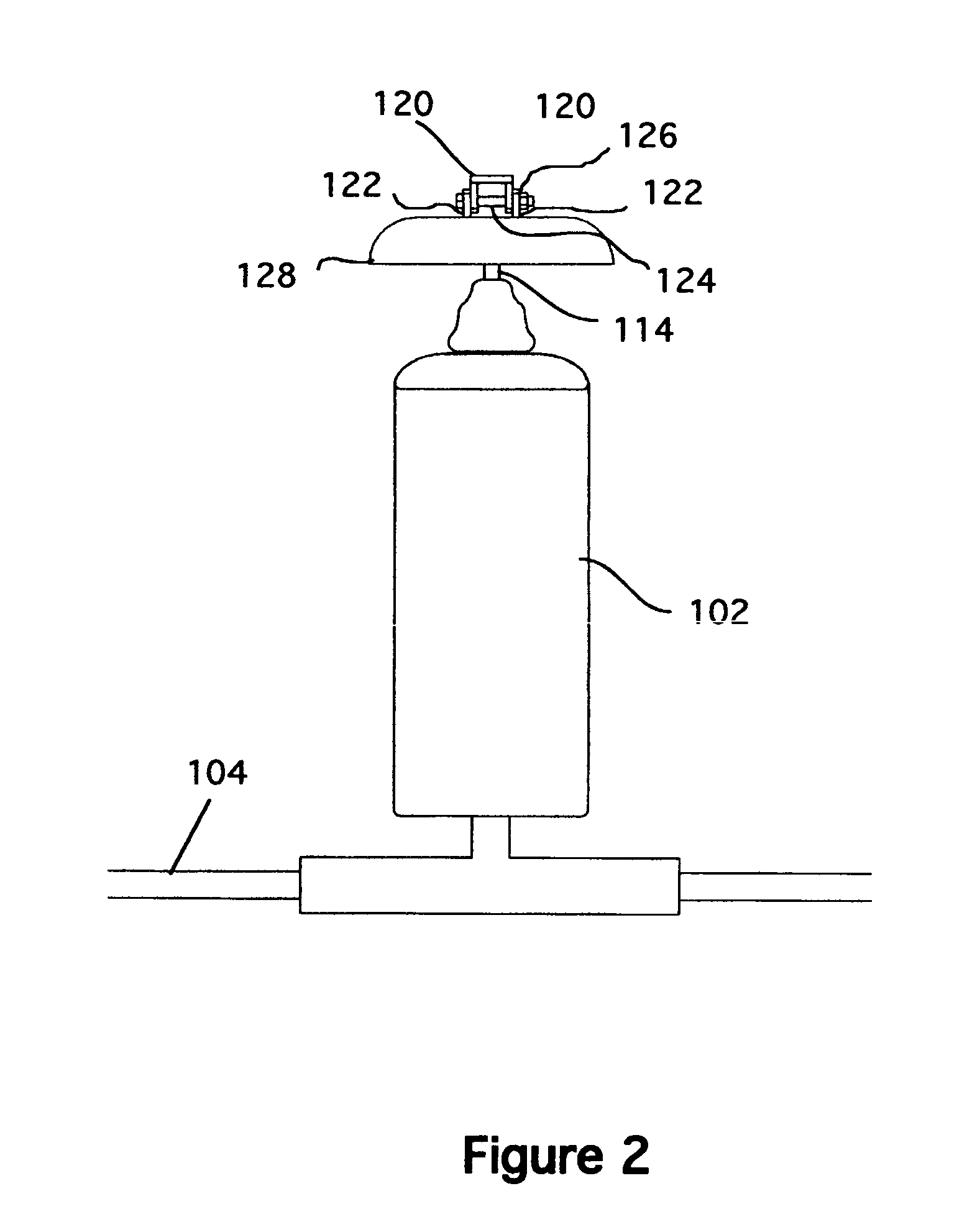
[0038]FIG. 2 is an elevation of the I-string insulator assembly 102 looking perpendicular to the wires 104. The fuse body 112 is attached to the tower using at least two vangs 120 on the tower with corresponding vangs 122 on the fuse body. The fuse body 112 is attached to the ...


PUM


Abstract

A device for limiting loads on towers that limits loads only in the longitudinal direction and does not affect the manner in which vertical and transverse loads are resisted by the structure. The device incorporates a shield to prevent ice buildup that could affect its operation. It also has optional antifriction bearings to provide a consistent release force independent of the amount of ice that may accumulate on the wires. The device is of simple construction. The device includes an optional energy absorber, such as that used in U.S. Pat. No. 3,211,260 that can provide a resisting force that is within the longitudinal strength of the tower. The device includes both a mechanical fuse and an energy absorbing mechanism that is used to arrest the wire movement. The energy absorber can extend as much as 50 ft to safely absorb the energy released by broken wires with heavy ice coatings.

Description

CROSS REFERENCE TO RELATED APPLICATIONS[0001]This application claims the benefit under 35 U.S.C. 119(e) based on Provisional Application No. 60 / 637,577, filed Dec. 19, 2004.STATEMENT REGARDING FEDERALLY SPONSORED RESEARCH AND DEVELOPMENT[0002]Not ApplicableBACKGROUND OF THE INVENTION[0003]1. Field of the Invention[0004]This invention relates to a device that limits the longitudinal loads on an electrical transmission structure and particularly to a device to limit the longitudinal loads on an electrical transmission structure, which includes an energy dissipating mechanism that safely dissipates the energy released when a failure releases the tension in the wires.[0005]2. Description of the Prior Art[0006]On electrical transmission lines, longitudinal loads act parallel to the wires that carry electricity. Transverse loads act horizontally perpendicular to the wires and vertical loads act downward or upward. On the majority of transmission towers, the wires are suspended from the st...

Claims


Application Information

Patent Timeline
IPC IPC(8): H02G7/20
CPCH02G7/20
Inventor PEABODY, ALAN B.
Owner PEABODY ALAN B
Why Eureka
Try Eureka