
Combined generator with built-in eddy-current magnetic resistance

a combined generator and built-in magnetic resistance technology, which is applied in the direction of mechanical energy handling, synchonous clutches/brakes, magnetic circuit shapes/forms/construction, etc., can solve the problems of not being able to design a generator specially for the fitness apparatus, not being able to meet the needs of the user, so as to reduce the demand for vehicle body precision, reduce the cost, and increase the effect of efficiency

Inactive Publication Date: 2010-06-08
LIN LILY
View PDF9 Cites 37 Cited by
  • Summary
  • Abstract
  • Description
  • Claims
  • Application Information

AI Technical Summary

Benefits of technology

This solution enables flexible inertia adjustment without affecting braking force, reduces noise and resonance, enhances power utilization, and minimizes generator volume and production costs, providing a comfortable and efficient exercise experience.

Problems solved by technology

Meanwhile, the generator employed in the fitness apparatus was not popular.
Therefore, no generator specially designed for the fitness apparatus is available.
However, the automotive generator is not designed specially for the fitness apparatus.
As a result, there are many parts that do not comply with the features of the fitness apparatus.
Therefore, the problem of efficiency of the low rotational speed is often neglected when the automotive generator is developed.
1. In order to achieve the rise of the rotational speed, the one-stage transmission has to be changed in a two-stage transmission, thereby increasing the manufacturing difficulty and cost.
2. The high rotational speed causes a greater resonance and magnetic sound. It is much unfavorable for the people to use the fitness apparatus and the rehabilitation apparatus indoors since they normally do not like noise to disturb their mood.
3. Unlike the fitness apparatus, the automotive generator does not require the application of inertia. Therefore, no inertia flywheel is installed in the automotive generator. However, the automotive generator employed in the fitness apparatus brings the operator an uncomfortable feeling in using the apparatus.
4. The automotive generator has a greater length so that the vehicle body of the fitness apparatus and the rehabilitation apparatus is correspondingly wider. Therefore, the feet of the operator have to be opened to a greater extent, thereby causing discomfort in use.
However, it still has the following inevitable drawbacks:
1. The resistance source is mainly resulted from the reverse connection of the power source of the generator. When the resistance is required, the type of the original generator is converted into the type of an electric motor, thereby creating a force opposite to the movement direction for achieving a braking effect. However, this braking effect is not enough. In order to eliminate this drawback, the speed ratio has to be enlarged by increasing the rotational speed of the generator. Nevertheless, the increase of the speed ratio will create the drawbacks as depicted in points 1 and 2 of the automotive generator.
2. The vibration and the noise created by multiple resonance of the reverse connection of power depicted in point 1 will be more intensified.
3. The power of the generator is not always effectively utilized. In other words, one part of the power must be consumed and lost. Therefore, a great resistance has to be installed for consuming the redundant power, thereby increasing the cost and lowering the efficiency.
1. The efficiency is effectively increased such that the two-stage transmission of the fitness apparatus and the rehabilitation apparatus is changed into one-stage transmission, thereby ensuring a great reduction of cost.
2. The demand on the precision of the vehicle body is decreased due to the one-stage transmission, thereby reducing the failure rate of the whole vehicle.
3. The rotational speed of the generator is low due to the one-stage transmission, thereby effectively minimizing the resonance and the noise.
4. The flat structure is favorable for the design of the vehicle body and suitable for the fitness apparatus and the rehabilitation apparatus. In other word, the vehicle body can be made flatter. Meanwhile, it is not necessary for the operator to open his feet widely, thereby ensuring a comfortable exercise.
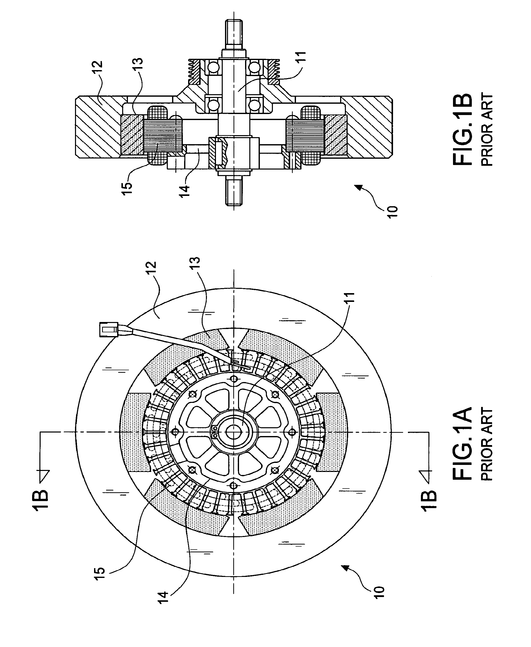
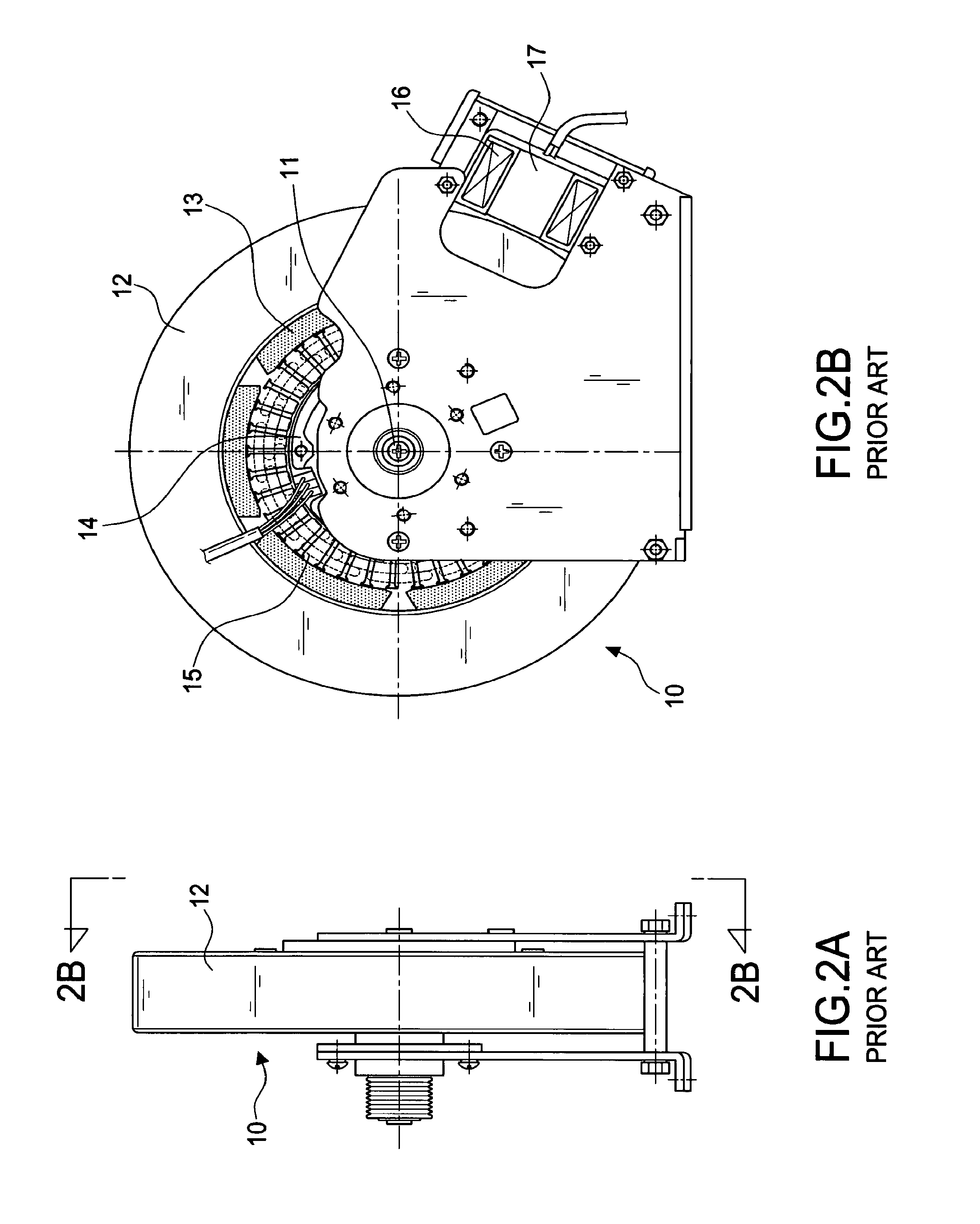
1. The fixed structure: A higher performance is only available when a uniform gap between the solenoid 16 (as well as the magnet core 17) and the inertia flywheel 12. Due to the fixed structure, the dimensions of the generator are not changeable according to the demand of each operator.
2. The magnet core 14 and the magnet core 17 of the generator are two separate and independent systems so that the production cost is higher.
3. The solenoid 16 is a separate body installed outside the inertia flywheel 12 so that the volume thereof is greater. This is unfavorable for the design of the whole vehicle body.

Method used


Image

  • Combined generator with built-in eddy-current magnetic resistance
  • Combined generator with built-in eddy-current magnetic resistance
  • Combined generator with built-in eddy-current magnetic resistance

Examples


Embodiment Construction

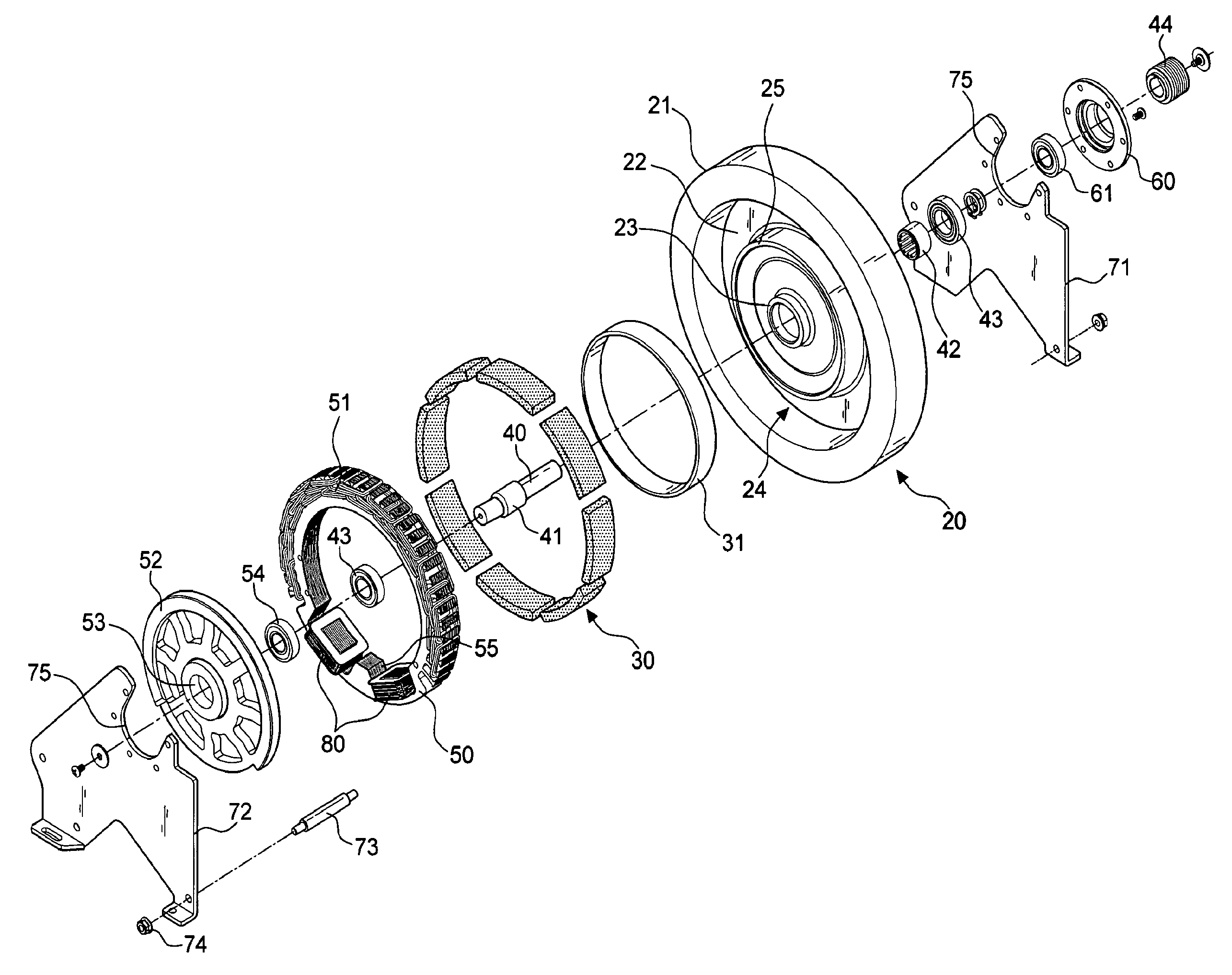
[0042]First of all, referring to FIGS. 3 through 6, a first embodiment of the invention includes an outward turning type inertia flywheel 20, a plurality of permanent magnets 30, a rotational shaft 40, a stator iron core 50, a sleeve 60, and a support bracket 70.

[0043]The outward turning type inertia flywheel 20 includes an external ring 21 and an internal wall 22. A wheel hub 23 is formed in the middle of the internal wall 22. Meanwhile, the outward turning type inertia flywheel 20 includes an opening end 24 at the external side thereof.

[0044]The permanent magnets 30 are disposed at the internal side of the external ring 21, thereby forming a rotor.

[0045]The rotational shaft 40 includes a bearing unit mounting thereon for supporting the flywheel 20. One end thereof is provided with a driven wheel 44 for imparting the rotational movement to the rotational shaft 40 and the flywheel 20. According to the embodiment, the bearing unit includes a unidirectional bearing 42 mounted on a mid...


PUM


Abstract

A combined generator with built-in eddy-current magnetic resistance including a rotor and a stator iron core with generating coils winding therearound. The rotor consists of an outward turning type inertia flywheel and permanent magnets. A self-generated supply is achieved when the flywheel is driven by a fitness apparatus or a rehabilitation apparatus. An internal ring (A magnet-conductive ring) between the wheel hub and the external ring of the flywheel is extended from the internal wall toward the opening end. The internal diameter of the stator iron core is greater than the external diameter of the magnet-conductive ring such that a magnetic field gap is created. At least one receiving portion is formed in at least one portion of the internal circumference of the stator iron core for receiving at least one solenoid. The power required by the solenoid is supplied by the self-generated system such that the solenoid produces a magnetic field (by input of the power), thereby providing the magnet-conductive ring coupled to and rotated on the inertia flywheel with an eddy-current magnetic resistance. In this way, a reverse resistance acts from the inside on the inertia flywheel such that a braking effect is achieved.

Description

BACKGROUND OF THE INVENTION[0001]1. Field of the Invention[0002]The invention relates to a combined generator with built-in eddy-current magnetic resistance, and more particularly to a generator that employs an outward turning type inertia flywheel to form a self-generated supply system. Meanwhile, one or several solenoids for producing the eddy-current magnetic resistance are integrally formed on the internal circumference of the stator iron core.[0003]2. Description of the Related Art[0004]The direct application of the automotive generator to the fitness apparatus and the rehabilitation apparatus that serves as a resistance system is traced back to the American fitness apparatus at the early stage. The American automotive industry is well developed. Meanwhile, the generator employed in the fitness apparatus was not popular. Therefore, no generator specially designed for the fitness apparatus is available. Due to the easy access and the mature technique, most of the fitness apparat...

Claims


Application Information

Patent Timeline
Patent Type & Authority Patents(United States)
IPC IPC(8): H02K21/22
CPCH02K1/146H02K49/06H02K21/222H02K1/16
Inventor LIN, LILY
Owner LIN LILY
Learn More