Heat radiating member mounting structure

Inactive Publication Date: 2010-06-08
YUAN DENG METALS IND
View PDF6 Cites 9 Cited by
  • Summary
  • Abstract
  • Description
  • Claims
  • Application Information

AI Technical Summary

Benefits of technology

[0006]The present invention has been accomplished under the circumstances in view. It is one object of the present invention to provide a heat radiating member

Problems solved by technology

During operation of a high-speed electronic device, much waste heat is produced.
However, increasing the numb

Method used


Image

  • Heat radiating member mounting structure
  • Heat radiating member mounting structure
  • Heat radiating member mounting structure

Examples


Example

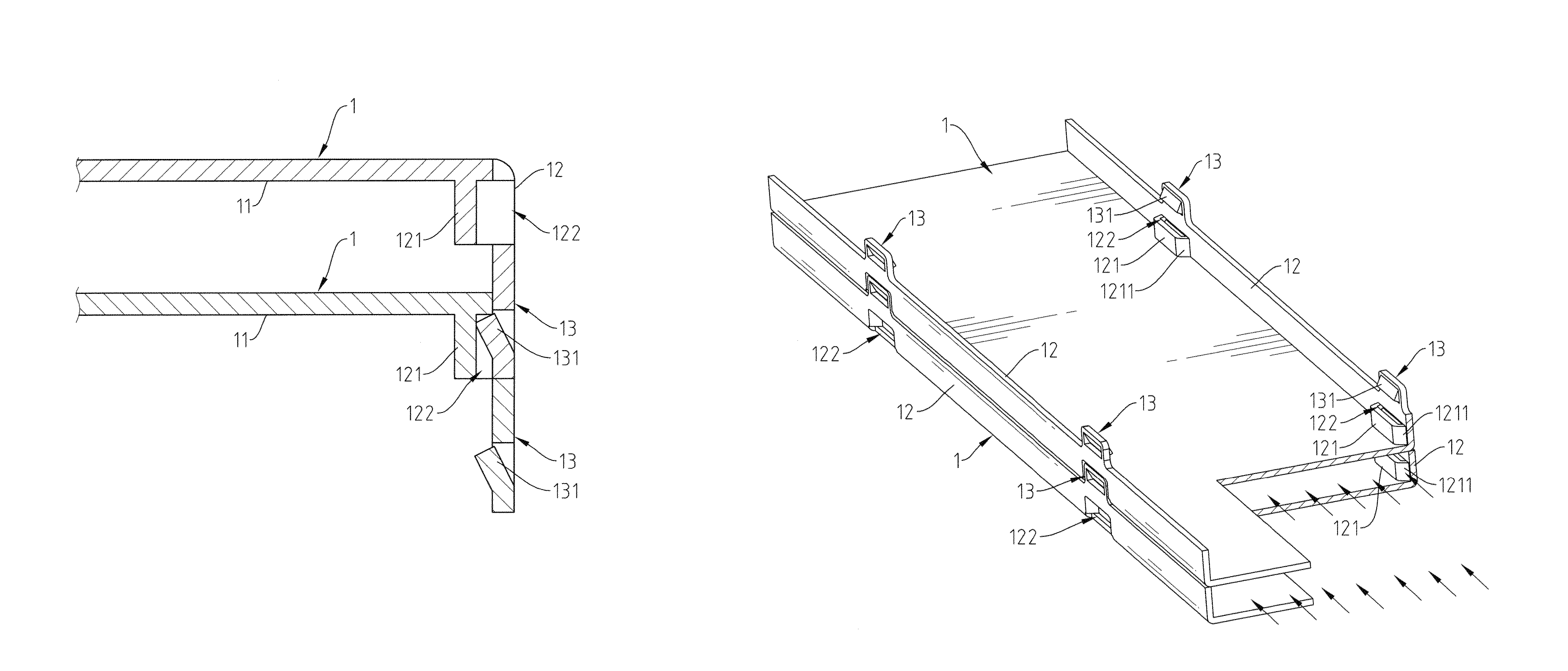
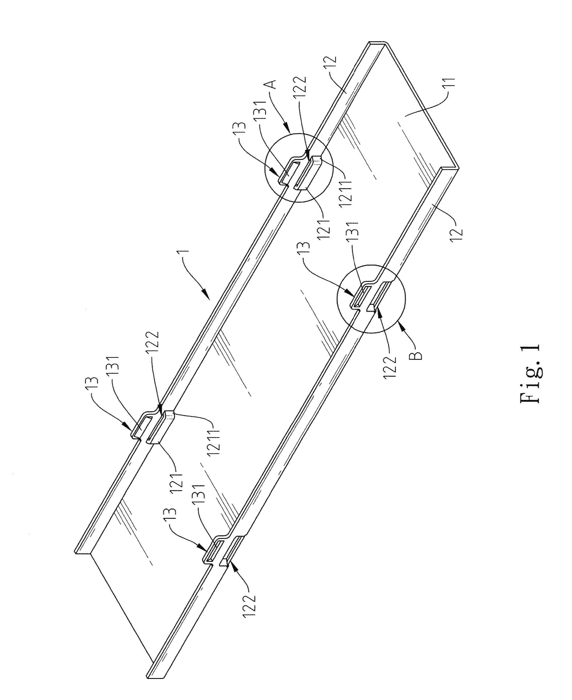
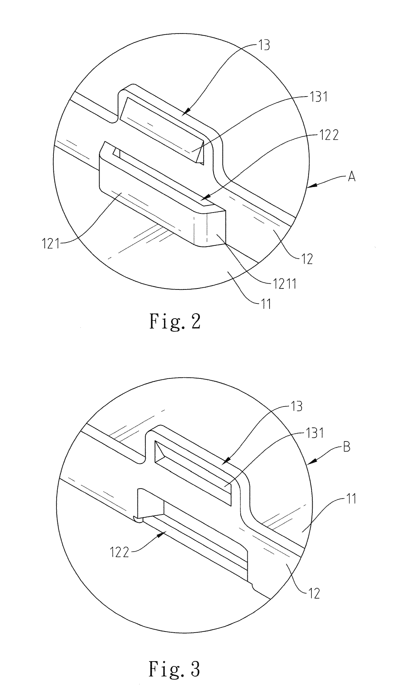
[0015]Referring to FIGS. 1˜3, a heat radiating member 1 is a single-piece member made of a thermally conductive sheet material (such as copper or aluminum sheet material), comprising a flat base 11 for attaching to the surface of a heat generating device (not shown) to dissipate heat energy from the heat generating device, two side flanges 12 respectively perpendicularly extended from two opposite lateral sides of the flat base 11 in a parallel manner. Each side flange 12 comprises a plurality of convex portions 121 arranged in a line, and a plurality of lugs 13 respectively disposed above the convex portions 121. The convex portion 121 has two beveled guide edges 1211 symmetrically disposed at two opposite lateral sides thereof, and a locating groove 122. Further, the convex portion 121 has its bottom side stopped against the flat base 11. The locating groove 122 is formed in an outer side of the convex portion 121, having a depth greater than the wall thickness of the side flanges...


PUM


Abstract

A heat radiating member mounting structure for enabling multiple heat radiating members to be fastened together in a stack without tools is disclosed. Each heat radiating member has convex portions and lugs formed on each of two upright side flanges at two sides of a flat base thereof such that multiple heat radiating members can be fastened together by means of engaging protruding portions of the lugs of one heat radiating member into locating grooves in the convex portions of another heat radiating member.

Description

BACKGROUND OF THE INVENTION[0001]1. Field of the Invention[0002]The present invention relates to heat dissipation technology and more particularly, to a heat radiating member mounting structure for use to dissipate heat from a heat generating device.[0003]2. Description of the Related Art[0004]An advanced electronic device has a high operation speed. During operation of a high-speed electronic device, much waste heat is produced. To maintain normal functioning of a high-speed electronic device, heat sink or cooler means may be used to carry waste heat away rapidly, avoiding the accumulation of heat. To enhance the heat dissipation performance of a heat sink, the heat spreading surface area must be relatively increased. Increasing the number of heat radiating sheet members or radiation fins can increase the heat spreading surface area. However, increasing the number of heat radiating sheet members or radiation fins of a heat sink relatively lowers the fabrication speed.[0005]Therefor...

Claims


Application Information

Patent Timeline
IPC IPC(8): H05K7/20
CPCH01L21/4882H01L23/3672H05K7/20418H01L23/4093H01L2924/0002H01L2924/00
Inventor HORNG, CHIN-HSING
Owner YUAN DENG METALS IND
Why Eureka
Try Eureka