Dynamic access priority scheme

a priority scheme and dynamic access technology, applied in the field of dynamic access priority scheme, can solve the problems of large collisions on the rach channel, network will see a surge in rach contention messages, and highly likely future collisions, and achieve the effect of lessening the impact of mbms on the rach

Active Publication Date: 2010-06-08
ALCATEL-LUCENT USA INC +1
View PDF23 Cites 24 Cited by
  • Summary
  • Abstract
  • Description
  • Claims
  • Application Information

AI Technical Summary

Benefits of technology

[0008]In one embodiment of the present invention, the maximum and/or minimum back off values, which indicate the maximum and minimum back off interval, form part of the service class information associated with each service class. Consequently, by providing different maximum and/or minimum back off values for different service classes and assigning user equipment a particular service class, a measure of control over the back off int...

Problems solved by technology

Since many users may subscribe to a MBMS service, the network will see a surge in RACH contention messages.
Such surges will cause large collisio...

Method used


Image

  • Dynamic access priority scheme
  • Dynamic access priority scheme
  • Dynamic access priority scheme

Examples


first embodiment

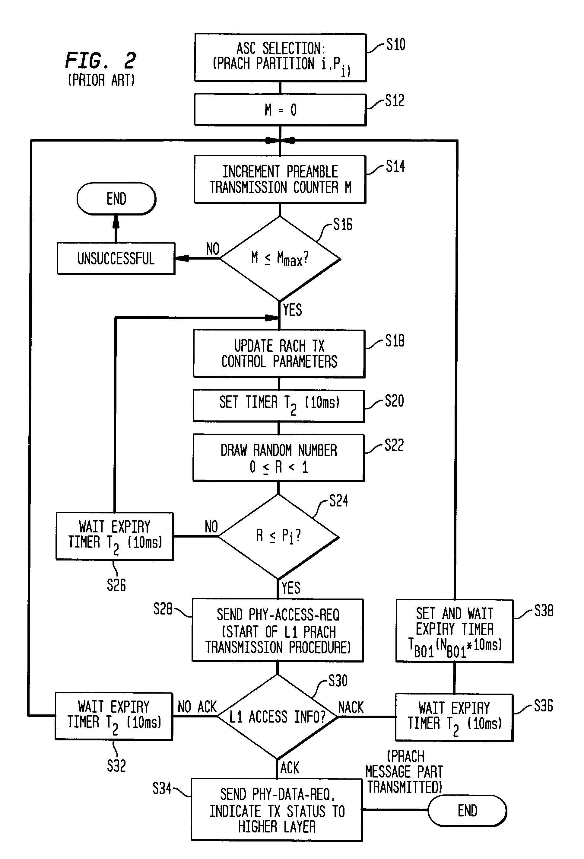
[0017]As discussed above, a UE decides whether to attempt transmission based on a RACH control parameter called a persistence value (transmission probability). According to the present invention, different persistence values are assigned to different ASCs. For example, higher priority ASCs are assigned larger persistence values. A larger persistence value improves the probability that transmission by a UE of that class occurs. Consequently, higher priority ASC UEs are more likely to attempt transmission than lower priority ASC UEs.

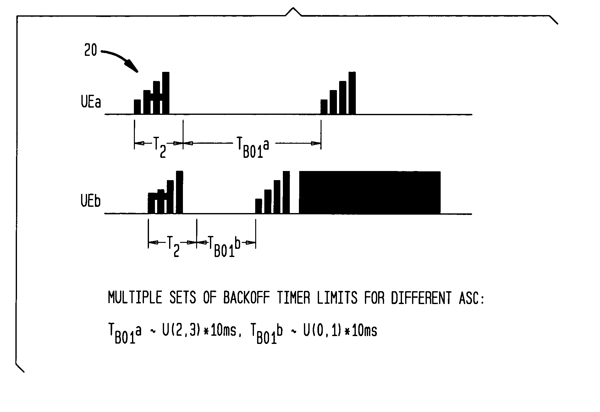
[0018]When a collision occurs (e.g., the UE receives a Non-ACKnowledgement signal from the network), the UE attempts to retransmit after a back off interval (step S38 in FIG. 2). The back off interval TBO1 is set equal to 10 ms times a back off value NBO1 randomly chosen between the maximum back off value NBO1max and the minimum back off value NBO1min. According to one embodiment of the present invention, different NBO1max values and / or NBO1min values are ...

second embodiment

[0023]In addition to, or independent of, the above described embodiments, in the present invention a different PRACH is allocated for a particular MBMS service, a group of MBMS services, or any MBMS service to prevent MBMS service related activities from impacting existing RACH related activities. Namely, the network assigns a PRACH to the UEs associated with a particular MBMS service, a group of MBMS services, or any MBMS service. In one version of this embodiment, the PRACH assigned is exclusively used for MBMS traffic; but the invention is not limited to this exclusivity.

[0024]As an additional aspect of this embodiment, the NBO1max for UEs assigned the MBMS PRACH is set larger than the NBO1max for one or more non-MBMS PRACHs to allow for more spread between different UEs trying to access the PRACH for MBMS service(s). When used with the conventional methodology of FIG. 2, the network associates one NBO1max with each PRACH as described with respect to FIG. 2. However, when this se...


PUM


Abstract

In the dynamic access priority method, priority classes with different backoff delays are used to prioritize random access over shared channels and to reduce collision in the presence of a surge of random access requests. Service class information for a plurality of service classes is stored at user equipment. The service class information for a service class includes at least one of a maximum and a minimum back off value; the maximum back off value being indicative of a maximum back off interval and the minimum back off value being indicative of a minimum back off interval. At least one of a maximum and a minimum back off value is determined based on a selected service class of the user equipment, and a back off interval is determined based on the determined back off value. The back off interval indicates a period of time the user equipment waits before the user equipment attempts a transmission.

Description

BACKGROUND OF THE INVENTION[0001]Multimedia broadcast / multicast service (MBMS) is a point to multipoint service in which data is transmitted from a single source entity to multiple users. The main objective of MBMS study is to take advantage of the fact that the same data is transmitted to multiple users, so that network resources can be efficiently shared among users.[0002]Referring to FIG. 1, which shows a portion of the well-known architecture for MBMS within a 3GPP network, when MBMS data is available for delivery, a serving GPRS support node SGSN will send a MBMS notification to relevant radio network controllers RNCs. These RNCs will then ask NodeBs (also known as base stations) to send relevant paging messages to notify interested users via their equipment UEs. Some of these UEs will be in idle states, while others will be may be in a Cell_PCH state (a state in which the UE has been assigned a dedicated airlink with a NodeB) or URA_PCH state (a state in which the UE is still ...

Claims


Application Information

Patent Timeline
IPC IPC(8): H04B1/00G06F15/16H04B7/216H04W4/00H04W74/08
CPCH04W74/0875
Inventor CHUAH, MOOI CHOOJI, TINGFANGLUO, WEI
Owner ALCATEL-LUCENT USA INC
Why Eureka
Try Eureka