Self-locking door assembly

a self-locking, door technology, applied in the direction of wing accessories, wing fasteners, manufacturing tools, etc., can solve the problems of loading taking up any play in the hinges and latches, and achieve the effects of preventing rattling or shaking, increasing lateral clearance, and reducing the risk of tampering

Inactive Publication Date: 2010-06-15
STRIKE INDS
View PDF27 Cites 36 Cited by
  • Summary
  • Abstract
  • Description
  • Claims
  • Application Information

AI Technical Summary

Benefits of technology

[0006]A door assembly according to the invention holds itself closed under force when in a closed position and provides increased lateral clearance between the door and a door opening in an open position. The door assembly of the invention can also be configured to provide resistance to tampering by positioning all hinge components and all latch components at locations which are hidden from view and inaccessible from the exterior of the door assembly when the door is in a closed position. In the closed position, the hinges and latches of the assembly are also loaded under lateral force. Such loading takes up any play in the hinges and latches. This assures a tight fit between the door and the door frame and prevents rattling or shaking of the door assembly when it is in the closed position without the necessity of manufacturing the hinges or latches to small dimensional tolerances.
[0009]In order to move the door from the partially closed position to the closed position, the hinge side of the door is forced closed so as to cause the second pivot joint to move past the center position toward the closed position. After the second pivot joint moves past the center position toward the closed position, the toggle linkage takes over, causing the door assembly to lock itself in the closed position. In the closed position, the hinge side of the door is closed firmly against the hinge side of the door frame and the latch securely engages the opposite side of the door. The toggle linkage biases the door to hold the door in the closed position under continuous force having a substantial component in a direction causing the door to bear down securely against the door frame. At least one of the latches preferably includes a tab engageable with the underside of the door frame. All components of the latches, including any fasteners used to mount them, are preferably located completely interiorly of the door assembly when the door is closed. By engaging the underside of the door frame, the tabs resist prying or pulling the free end of the door away from the door frame when the door is in the closed position. The tab is inaccessible, and hidden from view, from the exterior of the door assembly thereby helping to make the door assembly resistant to tampering. The hinges are preferably mounted so as to also be inaccessible and hidden from view from the outside of the door assembly when it is in the closed position.

Problems solved by technology

Such loading takes up any play in the hinges and latches.

Method used


Image

  • Self-locking door assembly
  • Self-locking door assembly
  • Self-locking door assembly

Examples


Embodiment Construction

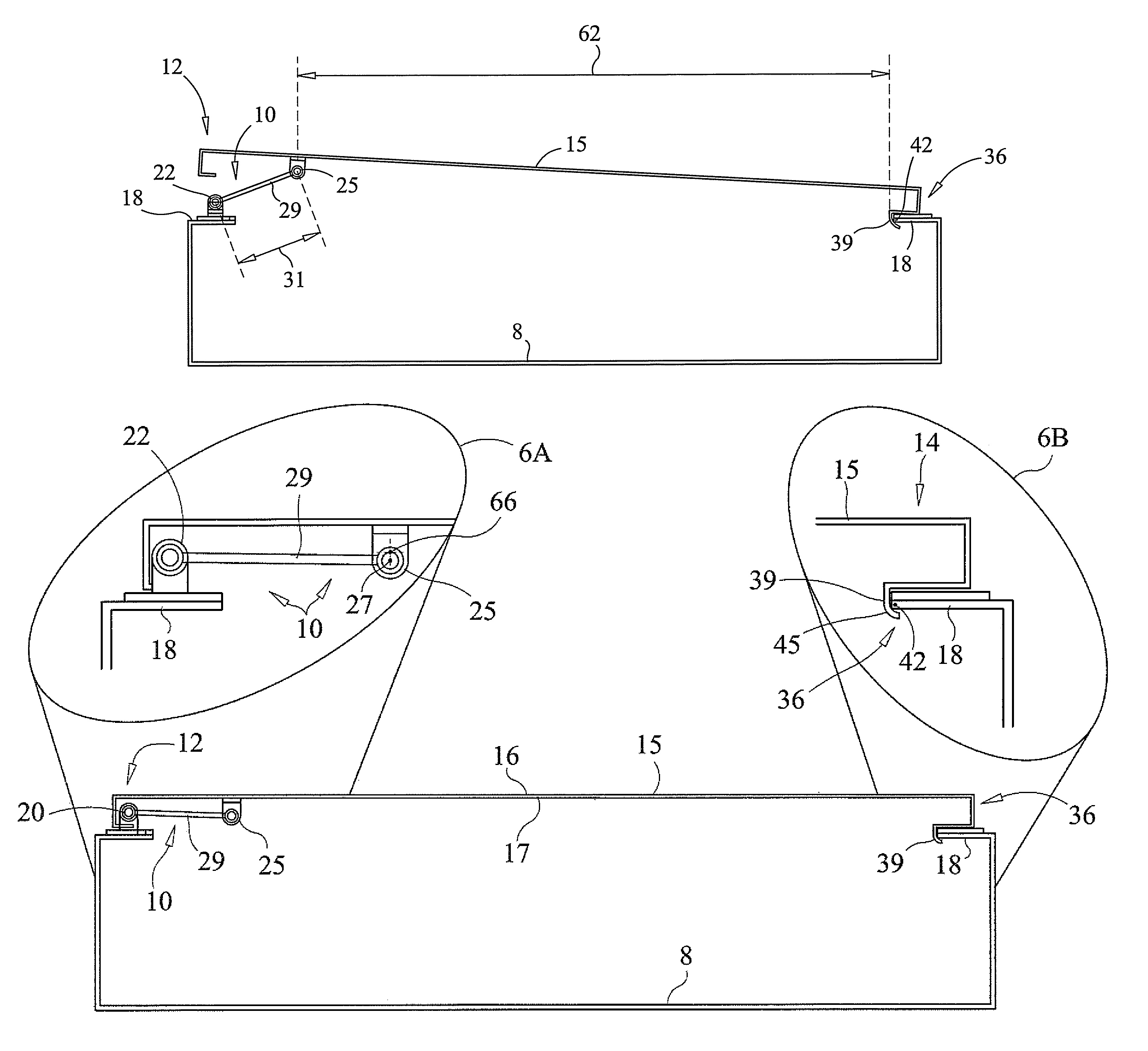
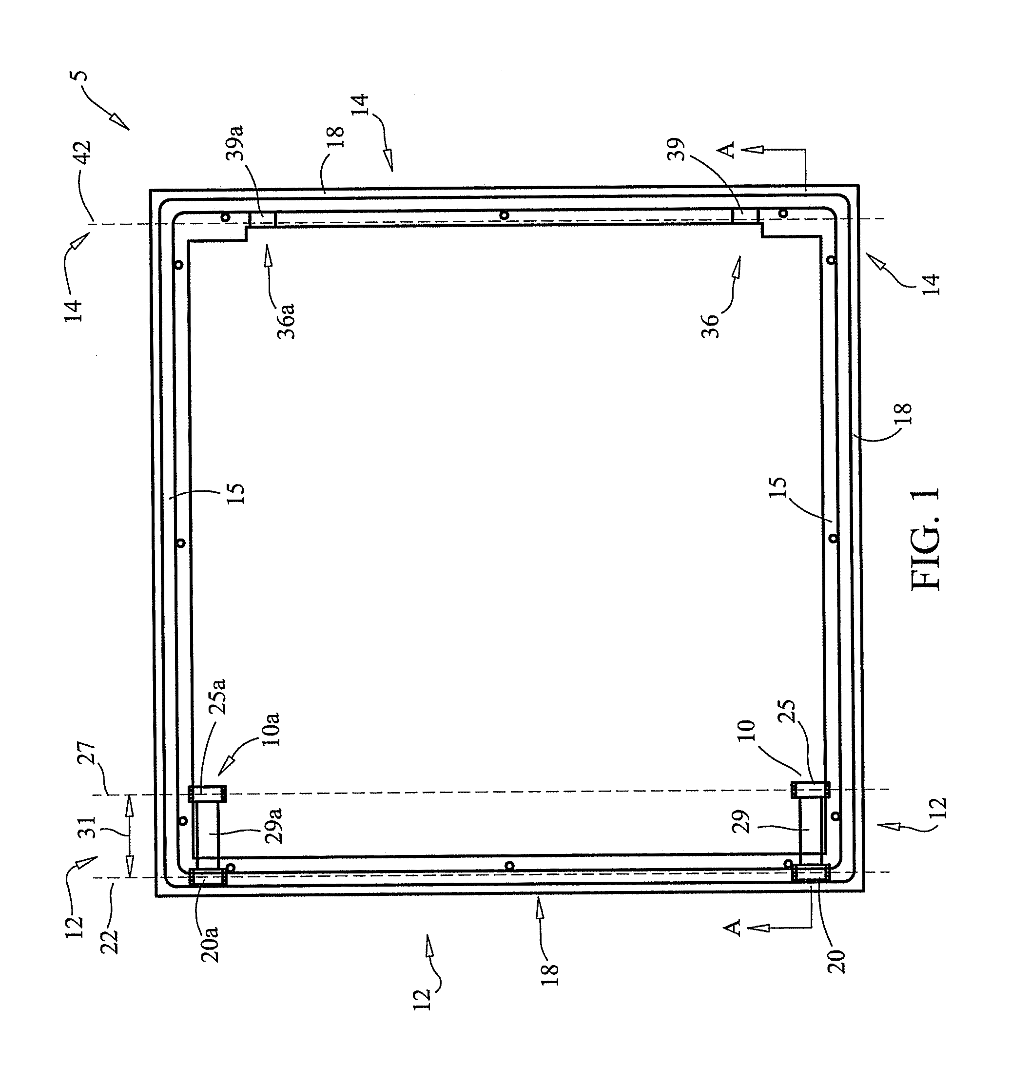
[0017]Referring initially to FIG. 1, a preferred embodiment of a door assembly 5 according to the invention is shown as used in the environment of a cabinet box 8. In FIG. 1, door assembly 5 is shown in a closed position. The door assembly 5 is selectively movable between an open position, a closed position, and various intermediate positions between the open position and the closed position.

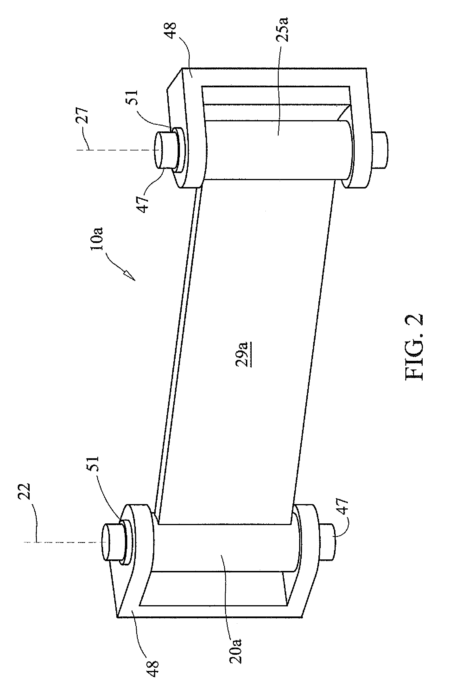
[0018]Door assembly 5 includes a door 15 having a hinge side 12 and a generally opposite side 14. Door 15 is mounted to a hinge side 12 of a door frame 18 by way of a pair of identical hinges 10 and 10a. One of the ends of each hinge 10, 10a is mechanically coupled to the underside of door 15 at an inside surface 17 of door 15 as shown in FIG. 6. As FIG. 6 also shows, door 15 has an outside surface 16 located opposite its inside surface 17. In order to resist tampering, hinges 10, 10a are preferably mounted by welding, suitably strong adhesives, and / or fasteners which are inaccessible from the e...


PUM


Abstract

A preferred embodiment of a self-locking door assembly includes a door whose hinged-side connects to one side of a door frame by at least one hinge having two pivot joints. One of the pivot joints is mounted to the door frame and the other is mounted to the inside of the door. The free end of the door carries a latch member which engages an underside of the opposite side of the door frame when the door is partially or fully closed. After the latch engages the frame, forcing the hinged side of the door closed causes the hinge to toggle, holding the door closed under force and takes up play in the pivot joints and / or latch. For security, the pivot joints and latch are concealed when the door assembly is closed.

Description

CROSS-REFERENCE TO RELATED APPLICATIONS[0001]This application claims the benefit of U.S. Provisional Application Ser. No. 60 / 975,716 filed Sep. 27, 2007 under 35 U.S.C. §119(e) for all commonly disclosed subject matter. U.S. Provisional Application Ser. No. 60 / 975,716 is expressly incorporated herein by reference in its entirety to form part of the present disclosure.STATEMENT REGARDING FEDERALLY SPONSORED-RESEARCH OR DEVELOPMENT[0002]Not Applicable.INCORPORATION BY REFERENCE[0003]Not Applicable.FIELD OF THE INVENTION[0004]The invention relates to a door assembly. More particularly, the invention relates to a door assembly which holds itself closed under force when in a closed position and provides increased lateral clearance between the door and a door opening when the door is in an open position.BACKGROUND OF THE INVENTION[0005]U.S. Pat. Nos. 7,152,936; 7,219,391; 7,175,243; 7,168,745; 7,118,185; 6,976,714; 6,971,687; 6,746,092; 6,578,884; 6,382,750; 6,374,651 each show door assem...

Claims


Application Information

Patent Timeline
Patent Type & Authority Patents(United States)
IPC IPC(8): E05D15/40
CPCE05C19/006E05D3/12E05F7/04H02B1/38E05Y2201/22Y10T16/53843Y10S292/17Y10S292/11E05Y2900/208
Inventor SELLATI, PATRICK A.
Owner STRIKE INDS
Why Eureka
Try Eureka